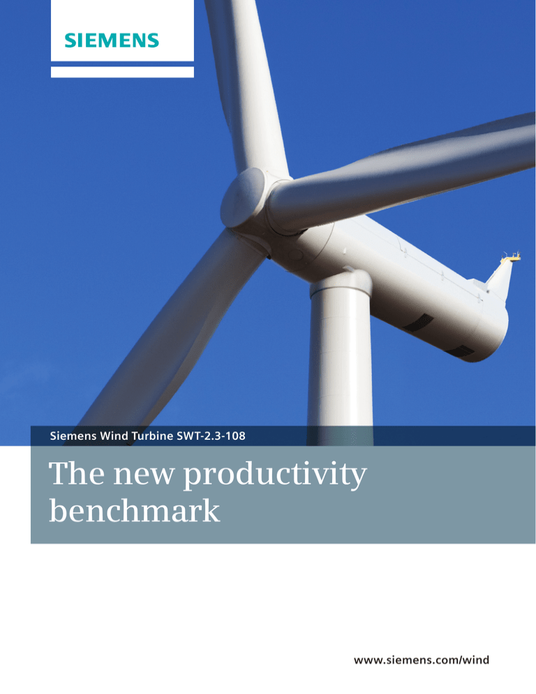
Siemens Wind Turbine SWT-2.3-108
The new productivity
benchmark
www.siemens.com/wind
The industry
standard, redefined
The Siemens 2.3-MW family has firmly established
itself as the tried and tested workhorse for reliability,
with a range of rotor diameters for different wind
conditions. Our new SWT-2.3-108 adds a new,
larger rotor to the family, setting a new standard
for productivity
Greater output from lower wind speeds
Since wind turbine technology was in its infancy, Siemens
has been a major driver of innovation. And with its
enhanced reliability and productivity in low to moderate
wind speeds, the new SWT-2.3-108 is yet another example
of the commitment to customers’ success.
Longer blades. More energy
In recent years, Siemens created a product line specifically
to extract more energy from moderate wind conditions.
The SWT-2.3-108’s innovative rotor blade design now
extends productivity even further. The new 108-meter
rotor with its unique blade properties is perfectly
optimized for sites with low wind speeds.
Your trusted partner
With its combination of robust and reliable wind turbines,
highly efficient solutions for power transmission and
distribution and a deep understanding of the entire
energy market, Siemens continues to be a leading
supplier. Long-lasting customer relationships based on
an excellent delivery record provide for a sound,
sustainable and profitable investment.
With over 140 years of experience in the energy sector,
a strong focus on renewables and a global network of
highly skilled and trained employees, Siemens has proven
itself to be a trustworthy and reliable business partner.
And it will continue to be in the future.
For superior availability, reliability and a lower levelized
cost of energy, look no further than the new Siemens
SWT-2.3-108 turbine.
Advanced blade technology
allows for longer lifecycles
and contributes to lower
levelized cost of energy
Superior performance provides higher yields
Optimum energy output at moderate wind conditions
Superior grid compliance
The SWT-2.3-108 wind turbine is designed to increase the
energy returns from sites with moderate wind conditions.
The advanced blade design, with a rotor diameter of
108 meters and pitch regulation, optimize power output
and increase control over energy output.
The Siemens NetConverter® system is designed for
maximum flexibility in the wind turbine’s response to
voltage and frequency variations, fault ride-through
capability and output adjustment. The advanced wind
farm control system provides state-of-the-art fleet
management.
High availability
Currently, the Siemens fleet of 2.3-MW wind turbines sets
the industry standard for availability. The SWT-2.3-108 will
build on the reputation for reliability that the market has
come to expect from a Siemens wind turbine.
High yield with minimal maintenance
Siemens optimizes the return on investment in its wind
turbines through intelligent maintenance that allows
high yield with low operational costs.
The rugged structural design, combined with an automatic
lubrication system, internal climate control and a
generator system without slip rings contributes to
exceptional reliability. The innovative design of the
SWT-2.3-108 allows for longer service intervals.
Proven track record
Siemens has a proven track record of providing reliable
wind turbines that last. The company’s first commercial
turbine was installed in 1980 and still operates today.
The world’s first offshore wind farm in Vindeby, Denmark,
was installed in 1991 and is also still fully operational.
In California, Siemens installed over 1,100 units between
1983 and 1990, with 97% still in operation today.
Siemens takes its commitment to reliability seriously and
prides itself on the long lifespan that its wind turbines
have demonstrated.
Siemens’ Turbine Condition
Monitoring® system instantly
detects deviations from normal
operating conditions
No compromise on reliability
SWT-2.3-108: The newest member of an extremely
reliable product family
Siemens wind turbines are designed to last. The robust
design of the SWT-2.3-108 allows for trouble-free output
throughout the complete lifecycle of the machine.
Instead of glueing the blades together from a number of
spars and shells, they are cast in a single process. This not
only enables both low weight and enormous strength,
there are no glue joins which could potentially expose
the blades to cracking and lightning damage.
Climate control within the nacelle protects vital
equipment from the outside environment. The wind
turbine also offers controlled-wear strategies for critical
components, which results in a further reduction of
maintenance costs.
Safety first
Safety is at the heart of all Siemens’ operations. From
production to installation, operation and service, Siemens
strives to set the standard in safety.
The fail safe capabilities within a wind turbine, combined
with Siemens’ superior lightning protection system, are
designed to enhance security for the turbine.
Advanced operations support
Given the logistical challenges associated with servicing
wind farms, Siemens has equipped its turbines with a
Turbine Condition Monitoring® system that reduces the
need for on-site servicing.
Siemens’ Turbine Condition Monitoring® system compares
the vibration levels of the main nacelle components with
a set of established reference spectra and instantly
detects deviations from normal operating conditions.
This allows Siemens to proactively plan the service and
maintenance of the wind turbines, as any unusual event
can be categorized and prioritized based on severity.
Using the knowledge gained from monitoring thousands
of wind turbines over the years, Siemens’ experts are
exceptionally skilled at analyzing and predicting
operational anomalies. This allows Siemens to proactively
plan service and maintenance activity as each event can
be categorized and prioritized based on severity.
Siemens can then determine the most appropriate course
of action to keep the wind turbine running at its best.
Technical
Specifications
SWT-2.3-108
Canopy
Rotor
Type
Position
Diameter
Swept area
Speed range
Power regulation
Rotor tilt
3-bladed, horizontal axis
Upwind
108 m
9144 m²
6-16 rpm
Pitch regulation with variable speed
6 degrees
Blade
Type
Blade length
Root chord
Aerodynamic profile
Material
Surface gloss
Surface colour
Self-supporting
53 m
3.4 m
NACA63.xxx, FFAxxx, SWPxxx
GRE
Semi-gloss, <30 / ISO2813
Light grey, RAL 7035
Full-span pitching
Active, hydraulic
Load-Supporting Parts
Hub
Main bearing
Main shaft
Nacelle bed plate
Nodular cast iron Spherical roller bearing
Alloy steel
Steel
Transmission system
Coupling hub - shaft
Coupling shaft - gearbox
Gearbox type
Gearbox ratio
Gearbox lubrication
Oil volume
Gearbox oil filtering
Gearbox cooling
Gearbox designation
Coupling gear - generator
Flange
Shrink disc
3-stage planetary/helical 1:91
Splash/forced lubrication
Approx. 400 I
Inline and offline
Separate oil cooler
PEAB 4456 (Winergy) or EH851 (Hansen)
Double flexible coupling
Mechanical brake
Type
Position
Number of callipers
Totally enclosed
Steel
Semi-gloss, 25-45, ISO2813
Light grey, RAL 7035
Generator
Type
Nominal power
Protection
Cooling
Insulation class
Asynchronous
2,300 kW
IP 54
Integrated heat exchanger
F
Grid Terminals (LV)
Nominal power
Voltage
Frequency
2,300 kW
690 V
50 Hz or 60 Hz
Yaw system
Aerodynamic brake
Type
Activation
Type
Material
Surface gloss
Colour
Hydraulic disc brake
High speed shaft
2
Type
Yaw bearing
Yaw brake
Yaw drive
Active
Externally geared slew ring
Passive friction brake
Eight electric gear motors with frequency converter
Controller
Type
SCADA system
Controller designation
Controller manufacturer
Microprocessor
WPS via modem
KK WTC 3.0
KK Electronic A/S
Tower
Type
Hub height
Corrosion protection
Surface gloss
Colour
Cylindrical and/or tapered tubular
80 m or site-specific
Painted
Semi-gloss, 25-45, ISO2813
Light grey, RAL 7035
Operational data
Cut-in wind speed
Rated power at
Cut-out wind speed
Maximum 3 s gust
3-4 m/s
11-12 m/s
25 m/s
59.5 m/s (IEC version)
Weights (approximately)
Rotor
Nacelle
60,000 kg
82,000 kg
4
1
5
6
7
8
9
12
10
11
13
3
2
14
15
16 17
18
19
Sales power curve
Nacelle arrangement
The calculated power curve data are valid for standard
conditions of 15 degrees Celsius air temperature,
1013 hPa air pressure and 1.225 kg/m3 air density,
clean rotor blades and horizontal, undisturbed air flow.
The calculated curve data are preliminary.
1.
Spinner
11. Generator
2.
Spinner bracket
12. Service crane
3.
Blade
4.
Pitch bearing
13. Meteorological
sensors
5.
Rotor hub
6.
Main bearing
7.
Main shaft
2000
8.
Gearbox
1800
9.
Brake disc
Power [kW]
2200
1600
10. Coupling
1400
1200
1000
800
600
400
200
0
0
5
10
15
20
Wind [m/s]
14. Tower
15. Yaw ring
16. Yaw gear
17. Nacelle bedplate
18. Oil filter
19. Canopy
20. Generator fan
20
Published by and copyright © 2011:
Siemens AG
Energy Sector
Freyeslebenstrasse 1
91058 Erlangen, Germany
Siemens Wind Power A/S
Lindenplatz 2
20099 Hamburg, Germany
www.siemens.com/wind
For more information, please contact
our Customer Support Center.
Phone: +49 180 524 70 00
Fax: +49 180 524 24 71
(Charges depending on provider)
E-mail: support.energy@siemens.com
Wind Power Division
E50001-W310-A184-X-4A00
Printed in Germany
Dispo 34804 c4bs No. 7491
MCS 12.11.1
Printed on elementary chlorine-free
bleached paper.
All rights reserved.
Trademarks mentioned in this document
are the property of Siemens AG, its affiliates,
or their respective owners.
Subject to change without prior notice.
The information in this document contains
general descriptions of the technical options
available, which may not apply in all cases.
The required technical options should therefore
be specified in the contract.

