Agenda Item 4 for 07-14
advertisement

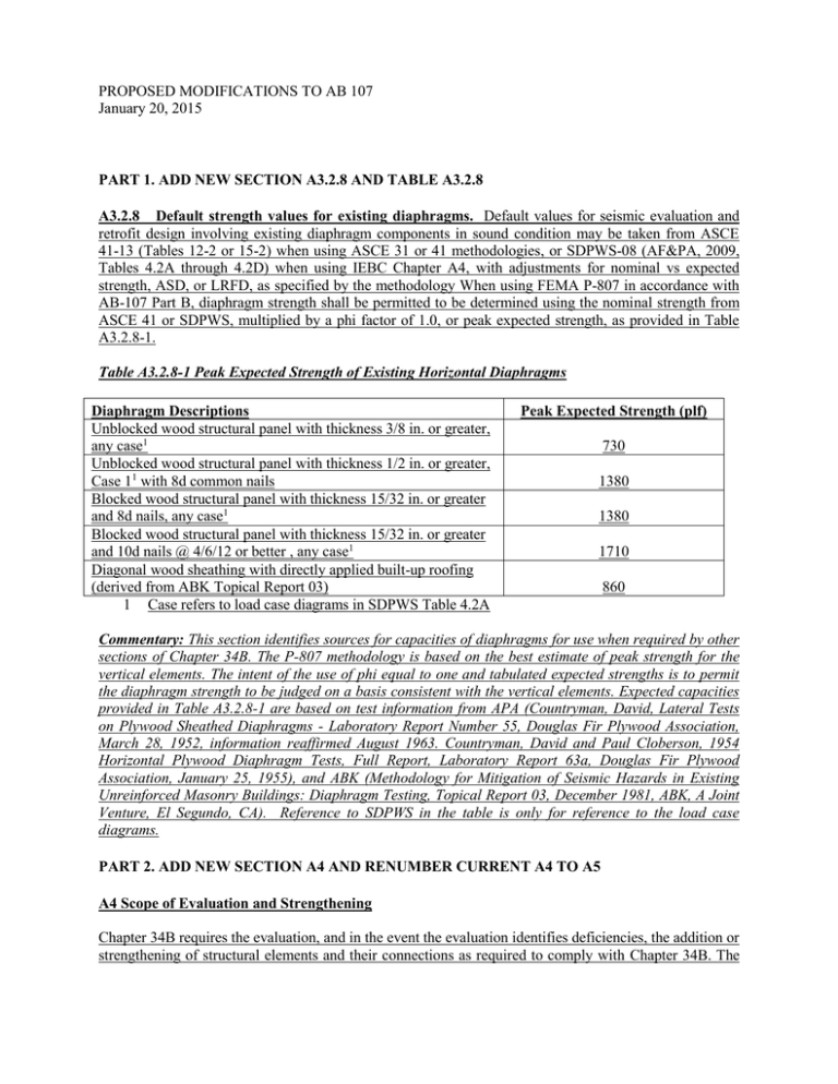
PROPOSED MODIFICATIONS TO AB 107 January 20, 2015 PART 1. ADD NEW SECTION A3.2.8 AND TABLE A3.2.8 A3.2.8 Default strength values for existing diaphragms. Default values for seismic evaluation and retrofit design involving existing diaphragm components in sound condition may be taken from ASCE 41-13 (Tables 12-2 or 15-2) when using ASCE 31 or 41 methodologies, or SDPWS-08 (AF&PA, 2009, Tables 4.2A through 4.2D) when using IEBC Chapter A4, with adjustments for nominal vs expected strength, ASD, or LRFD, as specified by the methodology When using FEMA P-807 in accordance with AB-107 Part B, diaphragm strength shall be permitted to be determined using the nominal strength from ASCE 41 or SDPWS, multiplied by a phi factor of 1.0, or peak expected strength, as provided in Table A3.2.8-1. Table A3.2.8-1 Peak Expected Strength of Existing Horizontal Diaphragms Diaphragm Descriptions Unblocked wood structural panel with thickness 3/8 in. or greater, any case1 Unblocked wood structural panel with thickness 1/2 in. or greater, Case 11 with 8d common nails Blocked wood structural panel with thickness 15/32 in. or greater and 8d nails, any case1 Blocked wood structural panel with thickness 15/32 in. or greater and 10d nails @ 4/6/12 or better , any case1 Diagonal wood sheathing with directly applied built-up roofing (derived from ABK Topical Report 03) 1 Case refers to load case diagrams in SDPWS Table 4.2A Peak Expected Strength (plf) 730 1380 1380 1710 860 Commentary: This section identifies sources for capacities of diaphragms for use when required by other sections of Chapter 34B. The P-807 methodology is based on the best estimate of peak strength for the vertical elements. The intent of the use of phi equal to one and tabulated expected strengths is to permit the diaphragm strength to be judged on a basis consistent with the vertical elements. Expected capacities provided in Table A3.2.8-1 are based on test information from APA (Countryman, David, Lateral Tests on Plywood Sheathed Diaphragms - Laboratory Report Number 55, Douglas Fir Plywood Association, March 28, 1952, information reaffirmed August 1963. Countryman, David and Paul Cloberson, 1954 Horizontal Plywood Diaphragm Tests, Full Report, Laboratory Report 63a, Douglas Fir Plywood Association, January 25, 1955), and ABK (Methodology for Mitigation of Seismic Hazards in Existing Unreinforced Masonry Buildings: Diaphragm Testing, Topical Report 03, December 1981, ABK, A Joint Venture, El Segundo, CA). Reference to SDPWS in the table is only for reference to the load case diagrams. PART 2. ADD NEW SECTION A4 AND RENUMBER CURRENT A4 TO A5 A4 Scope of Evaluation and Strengthening Chapter 34B requires the evaluation, and in the event the evaluation identifies deficiencies, the addition or strengthening of structural elements and their connections as required to comply with Chapter 34B. The intent, as described in Section 3401B, is to reduce the collapse risk of residential buildings with critically vulnerable lower stories, and to generally limit work to the ground story or to a basement or underfloor area that extends above grade where the most critical vulnerabilities are located. This critically vulnerable story is identified as the target story in AB 106, as the weak story and first story in FEMA P-807, and as the story having soft, weak, or open-front walls in IEBC Chapter A4. Whenever the term soft story, weak story, or target story is used in this administrative bulletin, it shall mean the critically vulnerable story as identified by Chapter 34B. The scope of evaluation and strengthening need only include the target story and, to the extent required by this bulletin, the diaphragm located immediately above the target story. Stories above the target story shall be considered in the evaluation as specified in this administrative bulletin and the adopted evaluation methodologies, but said portions need not be strengthened to comply with Chapter 34B. Evaluation or strengthening of the diaphragm located immediately above the target story is only required when existing vertical seismic force-resisting elements in the target story are strengthened, or new vertical seismic force-resisting elements are added to the target story. Where existing vertical seismic force-resisting elements in the target story are strengthened or new vertical elements are added to the target story, only the following conditions are required to be addressed: 1. At the location of force transfer between the diaphragm located immediately above the target story and each strengthened or new vertical element located in the target story, the diaphragm unit shear force transferred shall not exceed the diaphragm unit shear strength. 2. Where horizontal (straight) lumber sheathed diaphragms without integral hardwood floors occur in the diaphragm above the target story or portions thereof, the strength of such horizontal (straight) lumber sheathed diaphragms shall be evaluated and the diaphragm strengthened as required to meet the force requirements of Chapter 34B. Exception: One isolated area of not more than 150 square feet of horizontal sheathed diaphragm without hardwood flooring shall be permitted to occur in each dwelling unit without requiring evaluation of the diaphragm. Commentary: This section describes the intended scope of evaluation and strengthening for all acceptable evaluation methods (FEMA P-807, IEBC Appendix Chapter A4, and ASCE 41). It is not intended that global evaluation and strengthening of the diaphragm located immediately above the target story be required (except in the case of Item 2 below). Evaluation of the diaphragm's adequacy is only required when new vertical elements are added to the target story or existing vertical elements in the target story are strengthened. Chapter 34B is recognized as a hazard reduction measure intended to mitigate critically vulnerable lower stories. In the context of a hazard reduction policy that seeks to diminish the earthquake hazard risk while limiting the financial cost burden, the diaphragms are generally judged to pose a lesser life safety risk than deficient vertical elements located in the target story. Therefore consideration of diaphragm adequacy is limited to the two following circumstances: Item 1.Where new vertical elements are added or existing vertical elements are strengthened, completion of the load path requires demonstration that the expected forces in the vertical elements can be transferred to and developed into the diaphragm above. The designer is required to locally evaluate the adequacy of this part of the load path. The force in the vertical element(s) being connected to the diaphragm is divided by the length of the vertical element(s), or by the length of the vertical element plus collector if a collector is provided, to derive the unit shear demand. The shear demand is then compared to the unit shear capacity of the diaphragm. Where demand is greater than capacity, either the diaphragm is strengthened or the length of the collector is increased. This requirement is not intended to trigger an overall, global analysis of the diaphragm in order to demonstrate conformance to Chapter 34B. However this bulletin or the Ordinance do not prohibit the Design Professional from such an evaluation. The intent of this requirement is to encourage the introduction of a collector member that will adequately distribute forces into the diaphragm by reducing diaphragm shears in the vicinity of the vertical element. Alternatively to adding a collector, addition of a wood structural panel soffit of limited area to the underside of the diaphragm in the vicinity of an added or strengthened vertical element may be a feasible approach to diminishing shear demand in an existing diaphragm. The engineer can transfer all shear with the panel soffit, or can combine the capacities of the existing diaphragm and panel soffit sheathing using rules for combining materials for vertical elements contained in P-807, or any other rational analysis. The engineer is not required to check the diaphragm capacity at existing vertical elements that are not strengthened as it is assumed that the unit capacities of the existing vertical elements and diaphragm are comparable. (Shear transfer capacity between existing vertical elements and the horizontal diaphragm must be evaluated and provided if inadequate.) If this is not the case, and the existing vertical elements are considered as part of the lateral load resisting system (IEBC Chapter A4 does not consider existing walls as part of the lateral load system), it is appropriate for the engineer to consider provision of collectors or panel soffits at these locations. Item 2. Horizontal (straight) lumber sheathed diaphragms without integral hardwood flooring are thought to be considerably weaker and more flexible than other diaphragm systems, rendering horizontal (straight) sheathed diaphragms a deficiency that could compromise the building's ability to meet the objective of the soft story program even though there are no known collapses. As a result, in diaphragms or portions of diaphragms with horizontal (straight) sheathing, the strength of the diaphragm is to be compared to the global seismic demand throughout the diaphragm located immediately above the target story. Hardwood floors that are integral with the horizontal (straight) lumber sheathing are very common in older wood-frame buildings; the integral hardwood flooring (not newer “floating” wood floors) provides significant added strength and stiffness, such that the combination is not of significant concern. However, areas of local horizontal (straight) lumber sheathed diaphragms are commonly found in locations where the original hardwood flooring has been removed during remodel such as carpeted corridors or kitchens, and should be evaluated. The engineer’s walkthrough of a building with a horizontally sheathed diaphragms with integral hard wood flooring should be performed in sufficient detail to identify potential areas where flooring has been removed. An exception of up to 150 square feet per unit has been created to acknowledge areas that are too limited to affect overall building performance. Horizontal (straight) sheathed diaphragms are also found in the roof of single-story garage portions of the first soft story, common in many older San Francisco buildings that have hardwood floors elsewhere. The horizontal diaphragm capacity should be checked against global shear demand at these locations. PART 3. REVISE SUBSECTION B7.5.2 FOR FEMA P-807. B7.5.2 Second floor diaphragm Diaphragm immediately above the target story. The diaphragm located immediately above the target story shall be evaluated, and if found deficient, strengthened as needed to ensure that expected forces can be transferred between the diaphragm and first-story elements. required by Section A.4. Strengths for evaluating the diaphragm may be obtained from Section A3.2.8. PART 4. ADD SUBSECTION C1.1 TO SECTION C.1. FOR ASCE 41-13. C1.1 Diaphragm immediately above the target story. The diaphragm located immediately above the target story shall be evaluated and strengthened as required by Section A.4. Strengths for evaluating the diaphragm may be obtained from Section A3.2.8. PART 5. ADD SUBSECTION D1.1 TO SECTION D.1. FOR ASCE 41-06. D1.1 Diaphragm immediately above the target story. The diaphragm immediately above the target story shall be evaluated and strengthened as required by Section A.4. Strengths for evaluating the diaphragm may be obtained from Section A3.2.8. PART 6. ADD SUBSECTION E1.1 TO SECTION E.1. FOR ASCE 31-03. E1.1 Diaphragm immediately above the target story. A comparison of the diaphragm shear capacity to demand is not required at the diaphragm immediately above the target story. PART 7. IN SECTION F.1. FOR IEBC CHAPTER A4 STRIKEOUT EXISTING A403.8 AND REPLACE IT WITH A NEW SECTION A403.8. A403.8 Horizontal diaphragms. The strength of an existing horizontal diaphragm sheathed with wood structural panels or diagonal sheathing need not be investigated unless the diaphragm is required to transfer lateral forces from vertical elements of the seismic force-resisting system above the diaphragm to the elements below the diaphragm because of an offset in placement of elements. A403.8 Floor diaphragm immediately above the target story. The diaphragm immediately above the target story shall be evaluated and strengthened as required by Section A.4. Strengths for evaluating the diaphragm may be obtained from Section A3.2.8. Rotational effects shall be accounted for when asymmetric wall stiffness increases shear demand.


