Water Treatment Plant design
advertisement
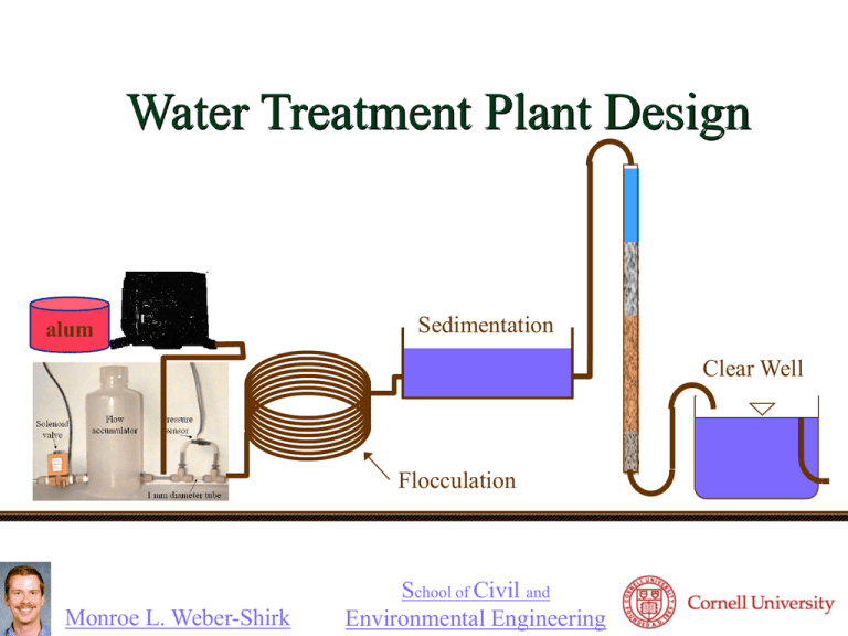
Water Treatment Plant Design alum Sedimentation Clear Well Flocculation Monroe L. Weber-Shirk School of Civil and Environmental Engineering Overview Safety Competition guidelines Trouble shooting guide Hydraulic challenges Surface tension Startup requirements Rapid Mix/Flocculation/Sedimentation Parting Pointers Laboratory Safety Safety hazards Electrical Chemical Aluminum Sulfate (alum) Buddy System Don’t go into any other areas of the environmental laboratory Professional behavior PPE: Safety glasses, lab coat Project Expectations Spend at least 4 hours per week working on WTP outside of class Keep an Excel time sheet (time in, time out, task, and weekly totals) for each of you (email weekly on Thursday to Jeff) Work together as a team and divide up tasks Spend time teaching each other what you are learning Professional Play! (Have fun!) Team Work Think efficiency You can’t all work on the same thing! Compare your team work to soccer players Don’t bunch up! Give each other permission to experiment with the plant Make a project schedule Water Treatment Plant Goals Best value (meets EPA turbidity standard with lowest annual cost of production for NYC) Longest continuous operation Best plant control logic Best plant design Best maintenance plan for cleaning sedimentation tank and flocculation tank Documentation of experimentation, data analysis, and appropriate plant modifications EPA Turbidity Standards As of January 1, 2002, turbidity may never exceed 1 NTU, and must not exceed 0.3 NTU in 95% of daily samples in any month. Our requirement will be that the turbidity be less than or equal to 0.3 NTU at all times The [(flow rate at the time of a turbidity violation) x (12 hours)] will be deducted as a penalty from the total plant production Note that if the TAs collect more than 2 samples per day it will be possible for the penalties to exceed the production! TAs will measure the flow rates and the turbidity several times per day and email results to the class Economics Capital costs Cost of building the various components building Controls and sensors Operation and Maintenance costs (O&M) Chemicals (alum) Electricity Labor Both capital and O&M costs contribute to the cost of the water produced We will only include the capital costs for this competition Competition Economics We will only include the costs for the processes that you can control The costs will be scaled as if your plant were full scale Otherwise the computer, data acquisition system, and control hardware would completely dominate the cost! The clear well and the flow accumulator will not be included in the economics Capital Cost Estimates Used for the Competition Item filters garnet sand anthracite rapid mix tank flocculation tank sedimentation tank lamella cost 8000 90 20 30 5000 2500 2000 unit surface area of filter volume of garnet volume of sand volume of anthracite volume of rapid mix tank volume of flocculation tank volume of sedimentation $/m2 $/m3 $/m3 $/m3 $/m3 $/m3 $/m3 20 $/m2 total surface area of lamella Calculating the cost of water from your plant if applied to NYC Calculate the cost of your plant Assign cost for 1 week of operation assuming 25 year life (1/1300th of total capital cost) Calculate the amount of water produced in the week of the competition Subtract any water that was produced within 12 hours of a turbidity standard violation Calculate the cost per m3 of water produced Calculate the annual cost for using your process to provide 60 m3/s to NYC When it doesn’t work! You are creating a complex system Any component that fails can lead to failure in the system How do you identify the source of a problem? Attempt to identify the events that could cause a failure in advance Scientific Method of Troubleshooting The Scientific method: Clearly identify the problem Create hypotheses Design experiments to test the hypotheses Draw conclusions based on the data How can you choose which components to test first? Intuition? Ask which component could cause the observed symptoms Requires an understanding of how the system works! Modular Approach How can you build a complex system with the greatest probability of ultimate success? Break a system down into its components and test individual pieces Only add components to the system after the components have been tested Begin with the system as simple as possible What would the simplest operating rules be? Add unit processes one by one State Machines What are the potential states for your water filtration plant? Off Down flow Backwash Media settle Filter to Waste Plant State Logic Assume your water treatment plant is currently backwashing. Under what conditions will the plant switch to a different state? Time greater than max set point Time greater than min set point and Above filter turbidity less than set point Clear well empty Output Device Control Some of the controls are either on or off depending on the state Centrifugal backwash pump Filter to waste valve Some of the controls have variable settings Alum pump rpm Flow control valve Alum pump rpm How might a plant operator want to control the alum pump? Pump rpm Alum stock flow rate Alum mass rate Alum concentration after mixing Fully automatic based on raw water turbidity What inputs are required? Flow Control Valve How should the solenoid valve be controlled? What role does the flow accumulator play? What will happen to the flow rate if the valve is opened for a short period of time? I D De ö P æ 1 u (t ) = K c çe + è TI å e ×Dt + T D ø Dt ÷ Closed loop control logic Hydraulic Challenges (getting the water to go where you want it to go) Leaks Connections not sufficiently tight Improvised connections lacking a good seal Overflows Caused by water not going where you thought it was going Open channel flows (air and water) – coming up Excessive head loss Tubing size too small Filter clogging Simplified WTP Schematic Can the flow accumulator be on the bench top? Yes What controls the sedimentation tank water level? Overflow weir Why does the water flow through the filter? Elevation difference How would you start up the plant and get water to flow through the filter the first time? Backwash How much head loss can the filter cause before the system fails? Sedimentation Flocculation Clear Well Improved WTP Why is this better? Max head loss? How could you measure head loss through the filter? Open Channel Flow Sedimentation Flocculation Clear Well Gravity Fg = r gl 3 0.080 0.075 0.070 0.065 0.060 0.055 0.050 0 20 40 60 80 100 Temperature (C) Fs = s l surface tension/weight Surface tension Surface tension (N/m) Relative Strength of Forces 100 10 Stable* 1 ? Unstable 0.1 0.01 0.1 * water column over air won’t break 1 10 length scale (mm) 100 Open Channel Flows: Water and Air All overflows tubes are open channel flow Minimum inside diameter for sink drain is 6.35 mm (¼”) Minimum inside diameter for line where water level moves up and down based on filter head loss is 9.5 mm (3/8”) What happens if the tubing isn’t large enough for open channel flow? WTP Leak and Overflow Prevention Clear well overflow line must be horizontal or sloping down (can’t go up and down) What happens if head loss through the filter increases too much? Check each tank or tube with an opening to the atmosphere and ask: What could cause an overflow at this location? How could we design the system to reduce risk of failure Turn off the manual supply valve when you aren’t using the plant Make sure that all solenoid valves are off when the plant isn’t being used. WTP Plant Layout Design a plant layout that is easy to follow Tubing lengths can be changed so you can place your devices anywhere you want them Beware of large diameter horizontal tubes containing particles Why? WTP Startup Requirements Stamp module must be on the computer side of the bench divider Must prove that excessive head loss will cause the filter to backwash before causing a flood! Must show that backwash won’t empty clear well Must show that the plant switches between states correctly Pointers Pressure sensors must be kept dry (they can fail if one drop of water soaks into the terminals) Use manual valves to make it easy to drain tanks Make sure you are using the most recent method file in your folder! Save a new version of the method file every time you make changes Label all processes Label the alum stock bottle Label all containers containing fluids Operating Criteria Initial down flow rate of 5 m/h (40 ml/min) If you increase the down flow rate make absolutely sure that the plant doesn’t overflow Use your water treatment plant design homework to calculate the best stock concentration of alum The best stock concentration might change if you significantly change the plant flow rate Plan to have someone check on the plant at least once per day (alum stock!) Rapid Mixing Goal? • Hydraulic Jump: Hydraulic Jump creates turbulence and thus help better mixing. • In-line flash mixing • Mechanical mixing Back mix impeller Poor Excellent Coagulant flat-blade impeller Inflow Chemical feeding Chemical feeding Inflow Flocculation Design Goal: produce large flocs from tiny particles Collision Mechanism: SHEAR We are doing research to find Shear that will cause floc to break apart (floc strength) Gq necessary to produce big floc (will dictate length of tube flocculator) Transfer into sedimentation tank must be done without increasing the shear How short can you make this? Given Gq, Q and d, Find Floc Tube Length 64Q G 3 d 3 True for laminar flow d2 q Q 4 Q L d 2L 4Q d 2 L 64Q 16 L Gq 3 4Q 3 d 3 d 3 dGq L 16 Turbidity after Sedimentation Increases with Maximum Shear 4 3.5 Residual Turbidity (NTU) As shear increases floc size decreases Small floc settle more slowly It is possible that some very small colloids are produced when large floc breakup Net result: higher shear causes higher turbidity after sedimentation Gmax 3 32Q d3 2.5 2 1.5 1 0.5 0 0 50 100 150 Gmax (1/s) 200 250 300 Sedimentation Tank Up flow through a sludge blanket at 50 m/day can create excellent quality water Additional flocculation occurs in the sludge blanket Lamella might increase particle capture Lamella spacing must be larger than the flocs you are trying to capture You can save money by making this as small as possible How will your Team Win? Produce the most clean water Keep costs down Efficient use of flocculation/sedimentation tanks Judicious use of filter to waste Only backwash when needed Well designed filter media (donated by US Filter) Document your design process Get your plant running ASAP so you can improve it before the competition begins. Good Engineering? How would you approach this task as a Cornell engineer in a way that is different then how you would approach it in elementary school? How do you learn about the physical world? Competition Submission Submit 5 copies by 5 pm on Thursday (May 5). Executive Summary A one page cover letter to the judges where you introduce your design firm, identify the members of your design team, and describe the important features of your water treatment plant. Final plant schematic all valves, sensors, tanks, and pumps with correct relative elevations. Clearly show the elevation of the laboratory bench top. Description of your design and your design process How did you size the unit processes in your plant? SHOW CALCULATIONS How did you test the plant? How did you use data that you acquired to modify the design? What are the special features of your plant that make it the best? Parting Pointers Hydraulics: water flows from higher potential energy to lower potential energy Leaks: fix them right away, clean up all spills immediately, keep bench dry, sensors and controls die when wet! Save incremental versions of process control method whenever you make changes
![[12] MB Emelko, Removal of viable and inactivated](http://s3.studylib.net/store/data/008455123_1-3af44e46ce1295c0cac0a6e37788609b-300x300.png)
