Document
advertisement

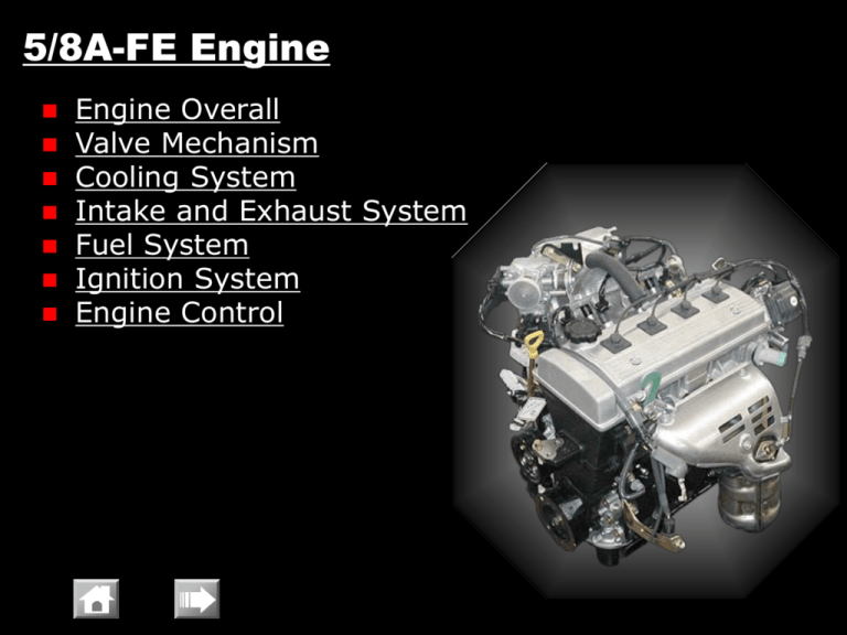
5/8A-FE Engine Engine Overall Valve Mechanism Cooling System Intake and Exhaust System Fuel System Ignition System Engine Control 5/8A-FE Engine -C Engine Overall • 4-cylinder, 16-valve, DOHC, STEP III or equivalent •5A-FE engine based on 8A-FE engine, displacement up 1.3 to 1.5 liters •Piston stroke only increasing 5/8A-FE Engine -C Engine Overall • Feature Fuel Pressure Regulator Location Changed Independent Injection Crankshaft Position Sensor TWC 5/8A-FE Engine -C Engine Overall • Engine specification Engine 5A-FE 8A-FE No. of Cylinders and Arrangement 4-cylinder, In-line 16-valve, DOHC 1498 (91.4) 1342 (81.9) 78.7 x 77.0 (3.10 x 3.03) 78.7 x 69.0 (3.10 x 2.72) 9.8 : 1 9.3 : 1 77 / 6,000? 63 / 6,000? 135 / 4,800? 122 / 4,400? 90 or more 5W-30 API SL-EC or ILSAC GF-3 Valve Mechanism Displacement [cm3 (cu. in.)] Bore x Stroke [mm (in.)] Compression Ratio Maximum Output [kW / rpm] Maximum Torque [N·m / rpm] Research Octane Number (RON) Oil Viscosity Oil Grade 5/8A-FE Engine Valve Mechanism • Overall -C •2 intake and 2 exhaust valves •2 camshafts Scissors Gear Belt Drive Outer Shim 5/8A-FE Engine -C Cooling System • Radiator and Cooling Fan – An aluminum radiator core and fan shroud integration type reservoir tank are used for weight reduction Reservoir Tank Aluminum Radiator Cooling Fan 5/8A-FE Engine -C Intake and Exhaust System • Exhaust Manifold (Manifold Converter) – Exhaust manifold is directly joined to the No. 1 TWC to ensure the proper warm-up performance Exhaust Manifold No. 1 TWC 5/8A-FE Engine -C Intake and Exhaust System • Exhaust Pipe – Stainless exhaust pipe is used for weight reduction Heated Oxygen Sensor Sub Muffler TWC No. 2 TWC No. 1 Ball Joint Main Muffler Ball Joint 5/8A-FE Engine -C Intake and Exhaust System • No. 2 TWC (Three-way Catalytic Converter) – Ultra thin wall, high-cell type TWC has been adopted. Thus it improves exhaust emission Wall Cell Pitch Thickness 1.27 mm 0.075 mm 5/8A-FE Engine -C Intake and Exhaust System • Converter Specification Converter No. 1 (Start-up Converter) No. 2 (Under Floor) Volume [cm3 (in.)] 1083 (66.1) Cell Density [cells/cm2 (cells/in2)] 62 (400) Wall Thickness [mm (in)] 0.115 (0.0045) 0.075 (0.0030) 5/8A-FE Engine -C Fuel System • Overall 4-hole Type Injector Pulsation Damper Fuel Pressure Regulator Location Changed Quick Connector 5/8A-FE Engine -C Fuel System • Fuel Pump – A compact fuel pump in which a fuel filter and pressure regulator are integrated in the module fuel pump assembly is used Fuel Cutoff Valve [Module Type Fuel Pump] Fuel Pump Fuel Filter Pressure Regulator Sender Gauge Pressure Regulator Fuel Pump 5/8A-FE Engine -C Fuel System • Fuel Returnless System – This system helps prevent the internal temperature of the Injector Pulsation fuel tank from rising, Dumper and reduces evaporative Delivery Pipe emissions Fuel : Only the quantity required of fuel is supplied : The fuel of a surplus quantity is returned Fuel Cutoff Valve Filter Pressure Regulator [Fuel Tank] Fuel Pump 5/8A-FE Engine -C Fuel System • Fuel Tank – The plastic made fuel tank and plastic filler pipe are used to reduce the weight Plastic Made Type Fuel Tank 5/8A-FE Engine -C Ignition System • ESA (Electronic Spark Advance) System Igniter Power Transistor IG Coil To Distributor Tachometer 5/8A-FE Engine -C Ignition System • Distributor – This distributor in the engine control system contains one pick-up coil (G signal) G Pick-up Coil Ignition Coil G Signal Rotor 5/8A-FE Engine -C Ignition System • Spark Plug – A compact with resister type is used Engine 5A-FE 8A-FE DENSO K16R-U11 K16R-U NGK BKR5EYA-11 Plug Gap 1.0-1.1 mm (0.039-0.043 in.) 0.7-0.8 mm (0.028-0.031 in.) Maintenance Pitch Every 20,000 km or every 24 months 5/8A-FE Engine -C Engine Control System • Main Components of Engine Control System Engine 5A-FE 8A-FE CPU 16-bit Emission Euro STEP III or equivalent Manifold Pressure Sensor Semiconductor Type Crankshaft Position Sensor (Rotor Teeth) Pick-up Coil Type (36-2) Camshaft Position Sensor (Rotor Teeth) Pick-up Coil Type (1) [It builds in Distributor] Throttle Position Sensor Linear Type Knock Sensor Piezoelectric Element Type Oxygen Sensor Heated Oxygen Sensor x 1 Injector 4-hole Type (Independent Injection) Ignition ESA IAC Valve Rotary Solenoid Type 5/8A-FE Engine -C Engine Control System • Crankshaft Position Sensor – The timing rotor of the crankshaft consists of 34 teeth, with 2 teeth missing NE Signal Plate (720CA) 2 Teeth Missing Crankshaft Position Sensor 10CA 2 Teeth Missing 5/8A-FE Engine -C Engine Control System • EFI (Electric Fuel Injection) – A D-type EFI system is used, which indirectly detects intake air volume by the manifold pressure sensor Manifold Pressure Sensor Sensor Unit (Semiconductor) 5/8A-FE Engine -C Engine Control System • EFI (Electric Fuel Injection) – An independent injection system (in which fuel is injected once into each cylinder) is used [Independent Injection] [Group Injection] Synchronous Injection Synchronous Injection #1 #3 #2 #4 Ignition Non-synchronous Injection Non-synchronous Injection Ignition 5/8A-FE Engine Engine Control System • EFI (Electric Fuel Injection) – Injection pattern are changed according to the engine condition and driving condition Water Temperature -C Independent Injection Group Injection Engine Speed Body Electrical Lighting Combination Meter Air Conditioner Navigation System TOYOTA Parking Assist System Power Window System Door Lock Control System Wireless Door Lock Remote Control Theft Deterrent System SRS Airbag System Accessories Body Electrical Lighting • Front Light Headlight (High/Low Beam) -C -R -T Position Light Turn Signal Light Front Fog Light -M Body Electrical -C -R -T Lighting • Rear Light Turn Signal Light Back-up Light Rear Fog Light Tail & Stop Light Reflex Reflector -M Body Electrical -C -R -T Lighting • Illuminated Entry System – This system is standard equipment on models with theft deterrent system +B TVSS ECU (Receiver is included) Interior Light Door Courtesy Switch (Each Door) Transmitter -M Body Electrical -C -R Combination Meter • General – Two types of combination meter are used Digital Type Analog Type (with Tachometer) -T -M Body Electrical -C -R -T -M Combination Meter • Speed Meter – Speed Sensor with ABS model Combination Meter Vehicle Skid Control ECU without ABS model -C, A/T model Combination Meter Speed Sensor Tire Combination Meter ECT ECU Speed Sensor Transaxle Speed Sensor Transaxle Body Electrical -C -R -T -M Combination Meter • Water Temperature Indicator – The indicator light change in accordance with the engine coolant temp. Indicator Light Condition - Engine Coolant Temp. Illuminate Below approx. 60 °C Blink Above approx. 117°C Not illuminate Other Body Electrical -C -R -T -M Combination Meter • Digital Display (Digital type only) – The image that is displayed on a display tube is reflected by a mirror, in which the magnified image is displayed Mirror Display Tube (VFD*) *: Vacuum Fluorescent Display Body Electrical -C -R -T -M Combination Meter • Rheostat (Digital type only) – Combination meter brightness is adjusted by pressing the rheostat switch – It has tail cancel function Combination Meter Brightness Tail Cancel Tail: OFF Bright Tail: ON Dark 1 3/4 1/2 1/4 1/4 1/8 1/16 1 Rheostat Switch Body Electrical -C -R -T Air Conditioner • General – Manual air conditioner is used Heater and Cooler (-C, -R) Cooler only (-T except Singapore, Brunei) Body Electrical -C -R Air Conditioner • Main Components SFA (Straight Flow Aluminum) Heater Core Sub-cool Condenser MS (Multi Tank Super Slim Structure) Evaporator Compact, Lightweight 10S11 Compressor -T -M Body Electrical -C Air Conditioner • Rear Heater Duct – The duct for rear seat is used for cold area spec. Rear Heater Duct Body Electrical -C GLX-i, GL-i only Navigation System • General – 6.5 inch LCD screen with pressure sensitive touch panel and DVD voice navigation Body Electrical -C Navigation System • System Diagram Video CD Changer Front Speaker (Driver Side) AVC-LAN GPS Antenna DVD-ROM Navigation ECU (Gyro Sensor included) RGB Signal Parking Brake Switch* Neutral Start Switch (AT) Back-up Light Switch (MT) Radio and Player with Display Combination Meter *:When the parking brake is not applied, the video CD is not playable Body Electrical -C Navigation System • Location GPS Antenna Radio and Player with Display Navigation ECU Video CD Changer Body Electrical -R 1.5G only TOYOTA Parking Assist System • General – Informs the driver of the distance between the sensors and the obstacles by sounding buzzer Pi… Pi… Body Electrical -R TOYOTA Parking Assist System • System Diagram and Operation – This system operates, when the shift lever is operated to the R position Neutral Start Switch R Position Ultrasonic Sensor (RH) Clearance Sonar ECU Clearance Sonar Buzzer Pi… Pi… Distance to obstacles Volume Switch Ultrasonic Sensor (LH) Body Electrical -R TOYOTA Parking Assist System • Operation – Buzzer sounding cycle Obstacle Distance Buzzer Sounding Cycle cm (in.) 0 – 40 (0 – 15.75) 40 – 60 (15.75 – 23.62) 60 –100 (23.62 – 39.37) ON OFF ON 75 75 OFF ON OFF 75 225 ms Body Electrical -R TOYOTA Parking Assist System • Location Ultrasonic Sensor (LH and RH) Clearance Sonar ECU Clearance Sonar Buzzer Volume Switch Body Electrical -R TOYOTA Parking Assist System • Ultrasonic Sensor – Detection ranges Approx. 1m (39.37 in.) Approx. 0.2m (7.87 in.) Approx. 0.3m (11.81 in.) Body Electrical -C -R -T Power Window System • General Model, Grade -C -R -T -M Driver door auto up/down with jam-protection function Driver door auto down Noavailable Front + Rear Front only Front + Rear GLX-i, GL-i, GL - - STD - DLX, DLX-i - - OPT - 1.5G, 1.5E STD - - - 1.5J - STD - - 1.5G, 1.5S 1.5E STD - - - 1.5J - - - STD 1.5G, 1.3E STD - - - 1.3 - - - STD -M Body Electrical -C -R Door Lock Control System • Function (with theft deterrent system only) – Speed-sensitive automatic door lock Combination Meter Ignition Switch TVSS ECU (Receiver is included) Door Lock Control Relay Door Lock M Motor (Each Door) -T -M Body Electrical -C -R -T Wireless Door Lock Remote Control • General – This system is standard equipment on models with theft deterrent system Hazard Warning Light Relay TVSS Siren TVSS ECU (Receiver is included) Door Lock Control Relay Door Lock M Motor (Each Door) Transmitter -M Body Electrical -C -R Theft Deterrent System • General – This system is used as following models Model -C GLX-i -R 1.5G, 1.5E -T 1.5G, 1.5S*1, 1.5E *2 -M 1.5G *1: Except Singapore, Brunei *2: Indonesia only -T -M Body Electrical -C -R -T Theft Deterrent System • System Diagram Ignition Switch Battery Door Lock Control Switch Security Indicator Key unlock Warning Switch Hazard Warning Light Relay Engine Hood Courtesy Switch Luggage Compartment Light Switch Door Courtesy Switch (Each Door) TVSS ECU TVSS Siren Starter Cut Relay Transmitter -M Body Electrical -C -R -T SRS Airbag System • General Destination Driver and Passenger Airbag -C GLX-i, GL-i, GL Grade *1 -R - -T -M Thailand, Indonesia 1.5S Grade Singapore, Brunei 1.5S, 1.5E Grade Driver Airbag ALL *1 *1 *1: *1 Non - 1.5G Grade ALL 1.5G Grade 1.5E Grade *2 1.5E, 1.5J Grade 1.5J Grade - - ALL with Pretensioner and Force Limiter *2: except Indonesia models Red Font: Optional Equipment Body Electrical -C -R SRS Airbag System • Front Airbag Deployment (with driver and passenger airbag) Airbag Sensor Assembly Electric G Sensor Electric Safing Sensor ON Front Airbag Sensor ON ON Front Airbag -T Body Electrical -C -R -T SRS Airbag System • Fuel Cut Control (Except 5A-FE, 8A-FE) – Airbag sensor assembly transmits the airbag deployment signal to engine ECU Airbag Sensor Assembly Airbag is deployed Engine ECU Fuel Cut M Fuel Pump Body Electrical -C -R Accessories • Sliding Roof – Power tilt and slide type sliding roof is used (manual operation only) Body Electrical -C -R -C: GLX-i -R: 1.5G Accessories • Telephone – In this system, telephone call is possible without releasing a hand from handle Front Speaker (Driver Side) Mobile Telephone Telephone Adapter Telephone ECU Wire (DOP) Telephone Microphone Body Electrical -C -R Accessories • Telephone – Location Telephone Adapter Telephone Microphone


