IT Essentials 5.0
2.2.4.5 Lab - Testing UTP Cables Using a Loopback Plug and a Cable Meter
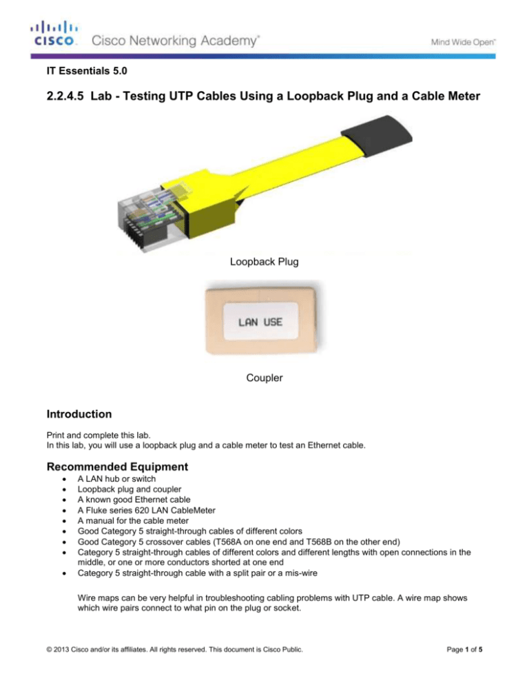
Loopback Plug
Coupler
Introduction
Print and complete this lab.
In this lab, you will use a loopback plug and a cable meter to test an Ethernet cable.
Recommended Equipment
A LAN hub or switch
Loopback plug and coupler
A known good Ethernet cable
A Fluke series 620 LAN CableMeter
A manual for the cable meter
Good Category 5 straight-through cables of different colors
Good Category 5 crossover cables (T568A on one end and T568B on the other end)
Category 5 straight-through cables of different colors and different lengths with open connections in the
middle, or one or more conductors shorted at one end
Category 5 straight-through cable with a split pair or a mis-wire
Wire maps can be very helpful in troubleshooting cabling problems with UTP cable. A wire map shows
which wire pairs connect to what pin on the plug or socket.
© 2013 Cisco and/or its affiliates. All rights reserved. This document is Cisco Public.
Page 1 of 5
IT Essentials
Chapter 2 Lab
Part 1: Loopback Plug
Step 1: Test an Ethernet cable using a loopback plug
a.
b.
c.
d.
Plug the loopback plug into one end of the coupler.
Plug one end of the Ethernet cable into the other end of the coupler.
Power on the hub or switch.
Plug the other end of the Ethernet cable into a port on the hub or switch.
After plugging the cable into the port, does a link light appear on the port?
If a link light does not appear, the problem is with the hub or switch. If the port displays a link light, then
the cable has passed the continuity test.
Part 1 of the lab is complete. Ask your instructor to verify your work.
© 2013 Cisco and/or its affiliates. All rights reserved. This document is Cisco Public.
Page 2 of 5
IT Essentials
Chapter 2 Lab
Part 2: Cable meter
Testing UTP Cables
Step 1: Set up the cable meter
On the cable meter, select the WIRE MAP function.
Ensure that the following settings (if available) are set properly.
Tester Option
Desired Setting - UTP
CABLE:
UTP
WIRING:
10BASE-T OR EIA/TIA 4PR
CATEGORY:
CATEGORY 5
WIRE SIZE:
AWG 24
CALIBRATE TO CABLE?
NO
BEEPING:
ON or OFF
Once the meter is set up, exit the setup mode.
Step 2: Test Cabling Procedure
When testing with a Fluke LAN CableMeter use the following procedure.
a. Place one end of the cable into the RJ-45 jack labeled UTP/FTP on the tester.
b. Place the other end of the cable into the RJ-45 female coupler (labeled LAN Use).
© 2013 Cisco and/or its affiliates. All rights reserved. This document is Cisco Public.
Page 3 of 5
IT Essentials
c.
Chapter 2 Lab
Insert the cable identifier (labeled Net Tool) into the other side of the coupler. The coupler and the cable
identifier are accessories that come with many cable meters.
Coupler and Cable Identifier
Step 3: Use the Wire Map function
The wire map function and a cable identifier can be used to determine the wiring of both the near and far end
of the cable. One set of numbers displayed on the LCD screen is the near end, and the other set is the far
end.
a. Perform a wire map test on each of the cables provided.
Fill in the following table based on the testing results for each Category 5 cable. For each cable, write
down the identifying number of the cable and the cable color. Also write down whether the cable is
straight-through or crossover, the tester screen test results, and a description of the problem.
Cable
No.
No.
Cable
Color
Straight-through or
Crossover
Displayed Test Results
(Note: Refer to the meter
manual for detailed
description of test results
for the wire map test.)
Problem/Description
Top:
Bot:
Top:
Bot:
Top:
Bot:
Top:
Bot:
Top:
Bot:
© 2013 Cisco and/or its affiliates. All rights reserved. This document is Cisco Public.
Page 4 of 5
IT Essentials
Chapter 2 Lab
Step 4: Use the Length Function
Using the tester LENGTH function, perform a basic cable test on the same cables used previously. Fill in the
additional information for each cable.
Cable No.
Cable Length
Tester Test Results (Pass/Fail)
© 2013 Cisco and/or its affiliates. All rights reserved. This document is Cisco Public.
Page 5 of 5


