KINEMATIC MECHANISM What is a Mechanism? In mechanical
advertisement
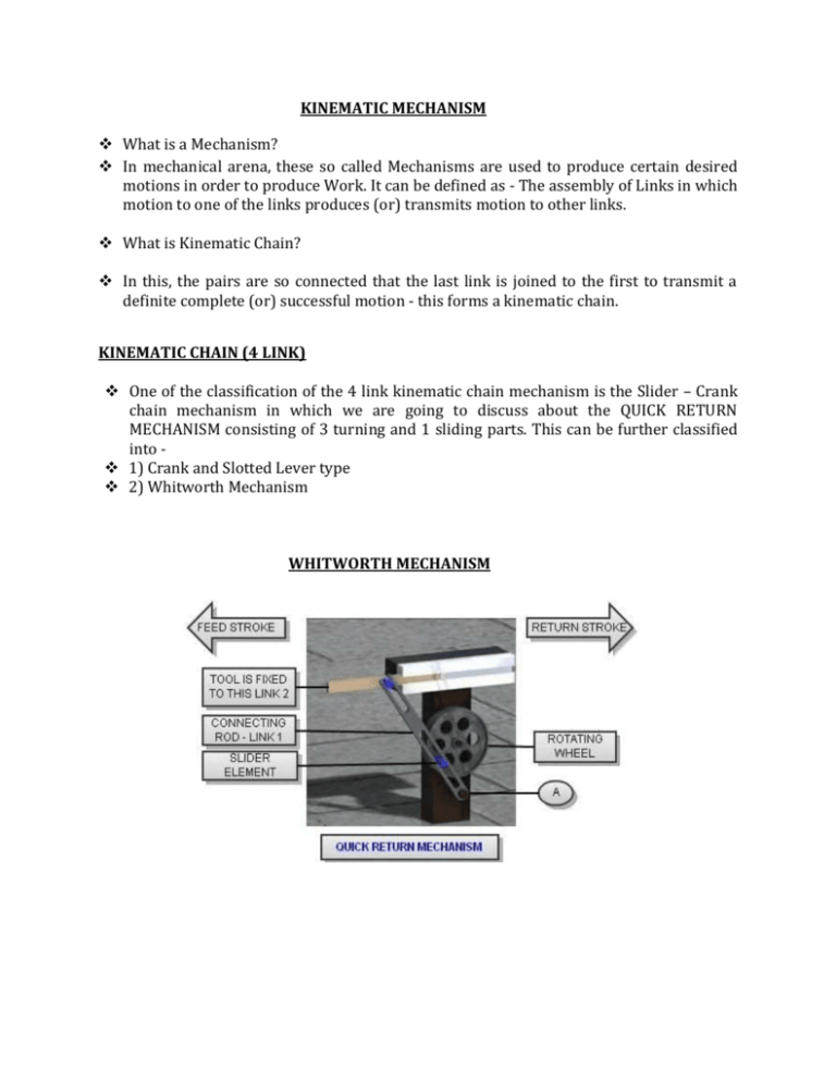
KINEMATIC MECHANISM What is a Mechanism? In mechanical arena, these so called Mechanisms are used to produce certain desired motions in order to produce Work. It can be defined as - The assembly of Links in which motion to one of the links produces (or) transmits motion to other links. What is Kinematic Chain? In this, the pairs are so connected that the last link is joined to the first to transmit a definite complete (or) successful motion - this forms a kinematic chain. KINEMATIC CHAIN (4 LINK) One of the classification of the 4 link kinematic chain mechanism is the Slider – Crank chain mechanism in which we are going to discuss about the QUICK RETURN MECHANISM consisting of 3 turning and 1 sliding parts. This can be further classified into 1) Crank and Slotted Lever type 2) Whitworth Mechanism WHITWORTH MECHANISM Description and Working:In general, these mechanical mechanisms are used to perform certain desired work. These mechanisms have a wide use in the machines used in the Production Industry. As the name suggests, the Quick Return Mechanism has its importance in its timing of the linear motion of the tool fixed to it. It consists of the Rotating Wheel that is fixed to the gear system and then the Motor. The Wheel consists of a small extension as a rod to the wheel which slides in the hollow connecting rod (Slider Element). The connecting rod is fixed at one end at A and the other end is connected to the link 2 which makes the tool slide. This link slides on the horizontal line of axis of the tool application which can be considered as a passage (or) a limited runway. The link 2 is connected to the tool with a pin. As this mechanism has a wide use in Slotting machine and Shaper machine – which creates linear slots on the work pieces, the feed of the tool is given a precise timing to obtain the perfect motion to remove the metal without any damage to the tool. Here, the speed is controlled by the gear mechanism. But when returning, the tool is lifted and is brought back to its initial position in almost double the speed used during feeding. This speed is achieved because the end point – A of the connecting rod being fixed and the other freely linked to transmit motion. During the start of feeding, the Slider element of the wheel in the connecting rod moves from top side to the bottom. But, during the return as the point – A is fixed, for a small angle of rotation of the wheel there is double the movement of the rod as there is less scope for the Slider to move in the Connecting rod. APPLICATION Above is a Slotter machine in which the tool is shown which can remove about 2 – 4 millimetres of metal at one stroke. During the return stroke the tool is lifted and is returned back as mentioned above.

