Chapter 17
advertisement
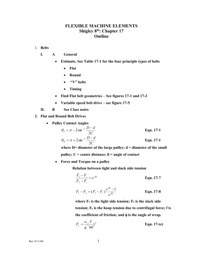
FLEXIBLE MACHINE ELEMENTS Shigley 8th: Chapter 17 Outline 1. Belts I. A General II. Estimate, See Table 17-1 for the four principle types of belts Flat Round “V” belts Timing Find Flat belt geometries – See figures 17-1 and 17-2 Variable speed belt drive – see figure 17-5 B See Class notes 2. Flat and Round Belt Drives Pulley Contact Angles Dd d 2 sin 1 Eqn. 17-1 2C Dd D 2 sin 1 Eqn. 17-1 2C where D= diameter of the large pulley; d = diameter of the small pulley; C = center distance; = angle of contact Force and Torque on a pulley Relation between tight and slack side tension F1 Fc e f F2 Fc Eqn. 17-7 F1 F2 ( F1 Fc ) e f 1 e f Eqn. 17-8 where F1 is the tight side tension; F2 is the slack side tension; Fc is the hoop tension due to centrifugal force; f is the coefficient of friction; and is the angle of wrap. Fc Rev 4/11/04 w V 2 ( ) g 60 Eqn. 17-(e) 1 Where V = dn/12 [ft/min]; w is the weight per unit length [lbf /ft]; g = 32.17 [ft/sec2]; d is the small diameter pulley [in]; and n is the rotation speed in rpm The difference between F1 and F2 is related to the torque on the pulley T F1 F2 D2 Where T = the torque; D = pulley diameter The tight and slack side tensions can be written 2e f F1 Fc Fi f Eqn. 17-10 e 1 2 F2 Fc Fi f Eqn. 17-11 e 1 F F2 Where Fi is the initial tension; Fi 1 Eqn. 17-(i) Fc 2 Which can also be written: T (e f 1) Fi Eqn. 17-9 D(e f 1) Note that if the initial tension is 0 then the torque transmitted is zero. The transmitted power ( F F2 )V H 1 Eqn. 17-(j) 33,000 Steps in analyzing a flat belt 1. Find exp (f) from belt geometry and friction 2. From belt geometry and speed find Fc 3. From T= 63025Hnom Ks nd/n find the necessary torque 4. From torque T find the necessary (F1)a – F2 =2T/D 5. Find F2 6. From equation 17-(i) find the necessary initial tension, Fi 7. Find the frictional development f’ < f. Use eqn. (17-7) solved for f’: f' 1 ln ( F1 ) a Fc F2 Fc 8. Find the factor of safety from n fs H a ( H nom K s ) Rev 4/11/04 2 The smaller pulley normally gives the limiting case for torque See examples 17-1 and 17-2on flat belt pulleys Flat metal belts see pages 883-885 and example 17-3 V-belts are able to provide more power transmission than flat belts For V-belts eqn. 17-7 becomes 3. V-Belts F1 Fc e f / sin F2 Fc Eqn. J&M 19-3a where is one half the V-belt included angle [usually =18] Gates Rubber Co equation for tight and loose side tensions F1 Fc e 0.5123 F2 Fc Eqn. 17-18 Where terms are the same as in eqn. 17-7. H d H nom K s nd Where Hd is the design power;Hnom is the nominal power; Ks is the service factor from table 17-15. Htab is the design power rating for certain conditions; it can be adjusted to other conditions with the following equation H a K1 K 2 H tab Eqn. 17-17 where Ha is the allowable power/belt, table 17-12 K1 is the angle of wrap correction factor, table 17-13 K2 is the belt length correction factor, table 17-14 For V-belts the centrifugal tension is given by Fc K c ( V 2 ) 1000 Eqn. 17-20 where Kc is from table 17-16 Power transmitted per belt based on F1 F2 is F F1 F2 Rev 4/11/04 3 63025 H d / N b n(d / 2) Eqn. 17-22 From equation 17-8 the largest tension is given by F1 Fc Fe f e f 1 Eqn. 17-23 F2 F1 F Eqn. 17-24 The initial tension Fi Fi F1 F2 Fc 2 Eqn. 17-25 The factor of safety is n fs H a Nb H nom K s Eqn. 17-26 See example 17-4 4. Timing Belts See section 17-4 5. Roller Chains See section 17-5 Note equations: 17-29, 17-30, (b), (c), and (d) Fatigue strength Power limitations for link plate and roller i. Link plate – eqn. 17-32 ii. Roller limited – eqn. 17-33 Center to center distance – eqn. 17-35 and eqn. 17-36 The allowable horsepower, Ha -- eqn. 17-37 The required horsepower transmitted -- eqn. 17-38 See Example 17-5 6. Wire Rope See section 17-6 Example 17-6 7. Flexible Shafts Rev 4/11/04 Read section 17-7 4
