Terms and Definitions
advertisement

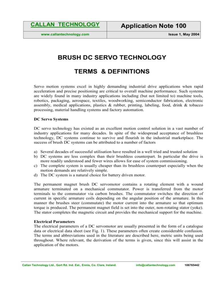
CALLAN TECHNOLOGY Application Note 100 www.callantechnology.com Issue 1, May 2004 BRUSH DC SERVO TECHNOLOGY TERMS & DEFINITIONS Servo motion systems excel in highly demanding industrial drive applications when rapid acceleration and precise positioning are critical to overall machine performance. Such systems are widely found in many industry applications including (but not limited to) machine tools, robotics, packaging, aerospace, textiles, woodworking, semiconductor fabrication, electronic assembly, medical applications, plastics & rubber, printing, labeling, food, drink & tobacco processing, material handling systems and factory automation. DC Servo Systems DC servo technology has existed as an excellent motion control solution in a vast number of industry applications for many decades. In spite of the widespread acceptance of brushless technology, DC systems continue to survive and flourish in the industrial marketplace. The success of brush DC systems can be attributed to a number of factors a) Several decades of successful utilisation have resulted in a well tried and trusted solution b) DC systems are less complex than their brushless counterpart. In particular the drive is more readily understood and fewer wires allows for ease of system commissioning. c) The complete system is usually cheaper than its brushless counterpart especially when the motion demands are relatively simple. d) The DC system is a natural choice for battery driven motor. The permanent magnet brush DC servomotor contains a rotating element with a wound armature terminated on a mechanical commutator. Power is transferred from the motor terminals to the commutator via carbon brushes. The commutator switches the direction of current in specific armature coils depending on the angular position of the armature. In this manner the brushes steer (commutate) the motor current into the armature so that optimum torque is produced. The permanent magnet field is set into the outer, non-rotating stator (yoke). The stator completes the magnetic circuit and provides the mechanical support for the machine. Electrical Parameters The electrical parameters of a DC servomotor are usually presented in the form of a catalogue data or electrical data sheet (see Fig. 1). These parameters often create considerable confusion. The terms and abbreviations used in the literature are described here, metric units being used throughout. Where relevant, the derivation of the terms is given, since this will assist in the application of the motors. Callan Technology Ltd., Gort Rd. Ind. Est., Ennis, Co. Clare, Ireland. info@callantechnology.com 106765442 Terms and Definitions Power (Rated) (Symbol – W, Units – Watts) Normally the continuous power rating of the motor at maximum speed for a particular winding Power = Torque (Nm) x Speed (rpm) x 2 x / 60 Watts Notes: 1) The torque used in the above formulae is that which is permitted at the maximum speed of the motor. This is usually defined by the maximum allowable degree of brush sparking and/or brush life, except in the case of very low speed windings 2) The continuous Stall torque does not apply at maximum speed because of commutation limits and the reduction of available torque due to brush and bearing friction as speed increases Max. Operating Speed (Symbol nmax, Units – rpm) Normally the speed at which the terminal voltage is at its maximum permitted level. (In a few cases the maximum speed is governed by mechanical considerations instead of voltage) Continuous Torque (Stall), (Symbol – Tc, Units – Nm) The continuous torque rating of the motor at continuous current, ambient temperature of 40°C and speed approaching zero rpm. This figure is based on pure DC current and must be reduced by the Form Factor when using amplifiers other than unity Form Factor. Continuous Torque Tc = Ic x Kt / F.F (Nm) Where: Ic = Continuous Current Kt = Torque Constant FF = Form Factor of Amplifier Used The value of the rated torque is determined by the max permissible temperature of the armature winding which is in turn determined by the insulation class of the motor. Typically this is one of the following Insul. Cl. A Insul. Cl. E Insul. Cl. B Insul. Cl. F Insul. Cl. H 105°C 120°C 130°C 155°C 180°C Peak Torque (Symbol – Tp, Units – Nm) The torque developed when the maximum permissible (peak) current is passed through the motor at standstill. Form Factor is not usually considered in this case, since peak current must not be passed through the motor for long periods. Callan Technology Ltd., Gort Rd. Ind. Est., Ennis, Co. Clare, Ireland. info@callantechnology.com 106765442 Peak Torque Tp = Ip x Kt (Nm) ** where : Ip = Peak Current ** Note that this figure is usually reduced in practice by the effect of Armature Reaction, and so the value of Tp given in the motor specification should be used where it is less than the value calculated from the above equation. Note also that if the amplifier used has a peak output of less than the value of Ip for a given motor, then the motor’s peak torque will be reduced pro rata. Theoretical Acceleration (Symbol m, Units – rad/sec/sec) This is the theoretical value of acceleration achieved away from standstill, when the motor is driven at peak current Ip, and so develops peak torque Tp. (with no load coupled to the motor) Theoretical Acceleration m = Tp/Jm rad/sec/sec Where : Tp = Peak Torque Jm = Motor Inertia Current at Continuous Torque (Symbol – Ic, Units – A) The current needed to produce continuous torque. This is an average value. Since any current other than pure DC contains an AC component, the continuous current is normally derated by the Form Factor. Current at Peak Torque (Symbol – Ip, Units – A) The maximum current that can be passed through the motor at standstill. This may be limited by the brushes or the winding. Maximum Terminal Voltage (Symbol – VT, Units V) The nominal maximum terminal voltage of the motor usually limited by the commutator. Terminal Voltage VT = (n/1,000) x Kb + Ia x Rm + Vb Volts Where : Ia = motor current at full speed Vb = Brush voltage drop, usually assumed to be approx. 2 Volts Note :- Where the motor does not have to run at its maximum terminal speed, the maximum terminal voltage will be reduced accordingly Torque Sensitivity (Symbol – Kt, Units – Nm/A) The relationship between the torque developed by the motor and the current flowing through it. This is a very important motor parameter. The effective value of Kt is reduced by the effect of armature reaction at high levels of current (see Peak Torque) Callan Technology Ltd., Gort Rd. Ind. Est., Ennis, Co. Clare, Ireland. info@callantechnology.com 106765442 (Z x x p) / (2 x n x a) Torque Constant = Nm/A where = flux/pole p = number of poles a = number of parallel paths through the armature Z = number of armature conductors For a given motor design , P and a are fixed, but Z may be varied : increasing the number of turns increases Z and hence Kt. This gives rise to the different windings A, B, C etc. quoted for each size of motor. At high levels of current Kt is reduced by the effect of armature reaction. This is the result of flux produced by the current in the armature windings partially opposing the flux produced by the field magnets. Back E.M.F. Constant (Symbol – Kb, Units - V/krpm) The voltage internally generated by the motor at 1,000 rpm. Back EMF Constant = (1000 x Z x x p) / (60 x a) V/krpm Note that from the equations for Back EMF constant and Torque Constant the important relationship Kb (V/krpm) = 104.7 x Kt (Nm/A) may be derived. Thus with a given motor design, it is not possible to change the Kb value without changing the Kt value by means of a winding change. Note also that Kb does not give the terminal voltage. DC Resistance at 25°C (Symbol – Rm, Units - ) The cold motor resistance, seen at its terminals, at room temperature. The temperature coefficient is typically 0.00388/°C Inductance (Symbol - Lm, Units – mH) The inductance of the motor , seen at its terminals Mechanical Time Constant (Symbol - m, Units - msec) The response of the motor to a fixed voltage applied across the armature, ignoring friction, at 25°C. Callan Technology Ltd., Gort Rd. Ind. Est., Ennis, Co. Clare, Ireland. info@callantechnology.com 106765442 This is the time for the motor to reach 63.2% of its final speed. The applied voltage must be such that the instantaneous current when the motor is at standstill does not exceed the peak current rating of the motor. Mech. Time Const. m = Jm x Rm X 1,000 / Kt2 msec where Jm = Motor Inertia Electrical Time Constant (Symbol - e, Units – msec) The electrical time constant of the armature at 25°C Elec. Time Const. e = Lm / Rm msec where Lm = Motor Inductance in mH Rm = Motor Resistance in Ohms The following parameters relate to the tacho option Voltage Sensitivity ( Symbol – Kg, Units – V/krpm) Tacho average output voltage per 1,000 rpm Voltage Ripple (Symbol – Vr, Units - % pk-pk/avg.) Tacho peak ripple expressed as a percentage of the average output. The frequency of the ripple is also given in cycles per revolution (cy/rev). Callan Technology Ltd., Gort Rd. Ind. Est., Ennis, Co. Clare, Ireland. info@callantechnology.com 106765442 DC Servomotor Tachometer C.D. 91535-300 Issue Written P.O'Beirne App'd. Sheet 1 of M4-2003-01A 1 02/01/2004 (TT2003) Motor Parameters (DC) Power 1 Winding Data Tol. Symbol Unit Rated P Watts hp A C D 100 90 / 0.134 0.121 Max. operating speed Max n max rpm 6000 4500 4700 Continuous Torque (stall) @40oC ambient Nom Tc Nm 0.45 0.45 0.34 * lb.ft 0.33 0.33 0.25 Peak Torque Nom Tp Nm 2.15 2.35 0.85 lb.ft 1.6 1.73 0.62 Theoretical Accl. Nom m rads/sec2 23,900 26,100 9400 Current @ cont. torque Rated Ic Amps 3.65 2.9 7* Current @ peak torque Rated Ip Amps 18 15.3 18 Max Vt volts 90 90 24 +/- 10% Kt Max. terminal voltage Torque Sensitivity Back EMF Constant # DC Resistance @ 25oC Inductance @ 1000Hz Time Constant at 25oC Nm/Amp 0.122 0.156 0.049 lb.ft/Amp 0.09 0.115 0.036 +/- 10% Kb V/Krpm 12.75 16.3 5.11 +/- 12.5% Rm Ohms 3.3 5.5 0.5 +/- 30% Lm mH 3 4.7 0.45 Mech m mSec 20 20 19 Elec e mSec 0.91 0.85 0.93 # DOES NOT INCLUDE CONTACT DROP Tachometer Parameters (TGF 1568 A) Winding Data A Voltage Sensitivity +/-10% Kg Volt ripple magnitude Max % Vr Volt ripple frequency Nom Elec. time constant DC Resistance Load Resistance Inductance V/Krpm pk-pk/avg cy/rev Nom 7.0 6 26 mSec +/- 12.5% Rg 43 Min RL 10000 +/-30% Lg mH 25 Basic Motor - Tachomoter Constants Rotor Inertia Weight Jm Wt Static Friction Thermal Time constant Viscous damping Z source kg.m2 0.00009 lb.ft.s2 0.000066 Kg (f) 2.2 lb 4.9 Tf Nm 0.03 lb.ft 0.022 TCT minutes F1 Nm/krpm lb.ft/krpm * Brush Limit Results 20 0.005 0.004 FIG. 1 Catalog Data Sheet for “M4-2003-01A” DC servomotor with integrated DC tachogenerator Callan Technology Ltd., Gort Rd. Ind. Est., Ennis, Co. Clare, Ireland. info@callantechnology.com 106765442


