1 - Suraj @ LUMS
1
1
1
0
1
Experiment No. 5
Objective
The objective of this lab is to design, build and use decoders.
Experiment A : 2-to-4 Decoder
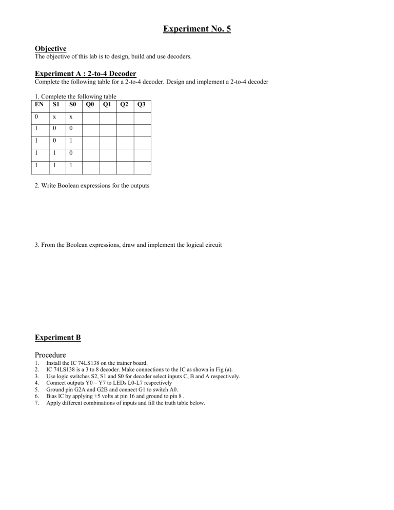
Complete the following table for a 2-to-4 decoder. Design and implement a 2-to-4 decoder
1. Complete the following table
EN S1 S0 Q0 Q1 Q2 Q3 x
0 x
0
0
1
1
1
0
1
2. Write Boolean expressions for the outputs
3. From the Boolean expressions, draw and implement the logical circuit
Experiment B
Procedure
1.
Install the IC 74LS138 on the trainer board.
2.
IC 74LS138 is a 3 to 8 decoder. Make connections to the IC as shown in Fig (a).
3.
Use logic switches S2, S1 and S0 for decoder select inputs C, B and A respectively.
4.
Connect outputs Y0 – Y7 to LEDs L0-L7 respectively
5.
Ground pin G2A and G2B and connect G1 to switch A0.
6.
Bias IC by applying +5 volts at pin 16 and ground to pin 8 .
7.
Apply different combinations of inputs and fill the truth table below.
E nable
G1(A0)
1
1
1
1
1
0
1
1
1
Select Inputs
S2 S1 S0
0
1
1
1
1
X
0
0
0
1
0
0
1
1
X
0
0
1
1
0
1
0
1
X
0
1
0
Decoder Outputs
L
0
L
1
L
2
L
3
L
4
L
5
L
6
L
7
0
1
1
1
1
1
1
1
1
Implement the following functions using the above circuit and any additional gates you may require. Draw the circuit diagram.
F(S2, S1, S0) =
m(2,4)
G(S2,S1,S0) =
m(3,7)
Fill the following truth table with outputs from your circuit
E nable
G1(A0)
Select Inputs
S2 S1 S0
X
0
0
0
0
1
1
1
1
X
0
0
1
1
0
0
1
1
X
0
1
0
1
0
1
0
1
Outputs
F G

