Page 1 of 4
M2 Interlock Controller
BASE
Description
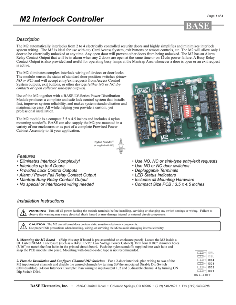
The M2 automatically interlocks from 2 to 4 electrically controlled security doors and highly simplifies and minimizes interlock
system wiring. The M2 is ideal for use with any Card Access System, exit buttons or remote controls, etc. The M2 will allow only 1
door to be electrically unlocked at any time. Any open door will prevent other doors from being unlocked. The M2 has an Alarm
Relay Contact Output that will be in alarm when any 2 doors are open at the same time or on 12vdc power failure. A Busy Relay
Contact Output is also provided and useful for operating busy lamps at the Mantrap Area whenever a door is open or an exit request
is active.
The M2 eliminates complex interlock wiring of devices or door locks.
The module senses the status of standard door position switches (either
NO or NC) and will accept entry/exit requests from Access Control
System outputs, exit buttons, or other devices (either NO or NC dry
contacts or open collector sink-type outputs).
Use of the M2 together with a BASE LV-Series Power Distribution
Module produces a complete and safe lock control system that installs
fast, improves system reliability, and makes system standardization and
maintenance easy. All while helping you provide a custom, yet
professional installation.
The M2 module is a compact 3.5 x 4.5 inches and includes 4 nylon
mounting standoffs. BASE can also supply the M2 pre-mounted in a
variety of our enclosures or as part of a complete Prewired Power
Cabinet Assembly to fit your application.
Nylon Standoff
(4 supplied with M2)
Features
• Eliminates Interlock Complexity!
• Interlocks up to 4 Doors
• Provides Lock Control Outputs
• Alarm / Power Fail Relay Contact Output
• Mantrap Busy Relay Contact Output
• No special or interlocked wiring needed
U
®
LISTED
• Use NO, NC or sink-type entry/exit requests
• Use NO or NC door switches
• Depluggable Terminals
• LED Status Indicators
• Includes all Mounting Hardware
• Compact Size PCB : 3.5 x 4.5 inches
Installation Instructions
!
!
Turn off all power feeding the module terminals before installing, servicing or changing any switch settings or wiring. Failure to
observe this warning may cause electrical shock hazard or may damage internal or external circuit components.
WARNING
The M2 circuit board does contain static sensitive electronic components.
Use proper ESD precautions when handling, wiring, or servicing the M2 to avoid damaging internal circuitry.
CAUTION
4
5
6
1. Mounting the M2 Board (Skip this step if board is pre-assembled on enclosure panel) Locate the M2 inside a
UL Listed NEMA 1 enclosure (such as a BASE LVPC Low Voltage Power Cabinet). Drill four 0.187" diameter holes
(3/16”) to match the four holes in the printed circuit board. Push the nylon standoffs supplied into each hole and
snap the PCB module into place. Mounting with double-sided tape is not recommended.
1
2
3
2. Plan the Installation and Configure Channel DIP Switches For a 2-door interlock, plan wiring to two of the
M2 input/output channels and disable the unused channels by turning ON the associated Disable Dip Switch
(ON=disabled). 3-Door Interlock Example: Plan wiring to input/output 1, 2 and 3, diasable channel 4 by turning ON
Dip Switch DD4.
ON<
ERL
DSL
DD4
DD3
DD2
DD1
>OFF
BASE Electronics, Inc. • 2856-C Janitell Road • Colorado Springs, CO 80906 • (719) 540-9697 • Fax (719) 540-9698
Page 2 of 4
M2 Interlock Controller
3. Entry/Exit Request Devices Connect wiring from Entry/Exit Devices (22 ga. min.) as shown in
Figure 1. All Entry/Exit devices must be the same type (all normally open dry contacts or all normally
closed dry contacts or all open collector sink outputs).
Configure the Entry Request Logic dip switch ERL.
ON = normally closed dry contact
Open Collector Outputs
Dry Contacts
of Access Control System
(normally open shown)
OFF = normally open dry contact or open collector
R2
R2
R3
R3
R3
DC COMMON
C
5. M2 Power Connect 12VDC power to the upper right terminals marked
12VDC as shown in Figure 2.
R4
Door Switches
DS1
DS2
DS3
DS4
DS1 C DS2 DS3 C DS4
4. Door Switches Connect wiring from Door Swiches (22 ga. min.) as
shown in Figure 1. All Door Switches must be the same type (all
normally open dry contacts or all normally closed dry contacts).
Configure the Door Switch Logic dip switch DRL.
ON = normally closed dry contact
OFF = normally open dry contact
***Warning*** - Any external + voltage accidently applied to the M2
Door Switch terminals may permantly damage internal circuits and void
warranty.
ENTRY
REQUESTS
2
3
4
R4
R4
1
R2
Entry/Exit
Request Devices
R1
C
Open collector sink outputs are outputs that
utilize an open collector transistor to “sink” or
switch the negative side of a device to DC Com.
Like any switch contact, an open collector output
will have a current limitation. In this case, the
device to be switched to DC Common is the M2
input terminal circuit, and the open collector output
must have a current limit of at least 25mA at 12VDC.
***Warning*** - Any external + voltage accidently
applied to the M2 Entry/Exit Request terminals may
permantly damage internal circuits and void warranty.
BASE
R1
R1
1
DOOR
SWITCHES
2
3
4
Dry Contacts
(normally closed shown)
M2
INTERLOC
Figure 1 - M2 Input Wiring
6. Alarm Output The M2 Alarm Relay form-C Output Contact is rated for 2A max. This relay is normally energized and therefore, also provides
an alarm when the M2 loses 12VDC power.
7. Busy Output The M2 Busy Relay form-C Output Contact is rated for 2A max. This relay is normally de-energized
and energizes whenever a door is open or an Entry Request is active. This is useful for operating lamp(s) at the mantrap area to signify to
the next user that the mantrap is in use. See wiring example shown in Figure 2.
8. Lock Control Outputs
(See Page 3)
Operation
1. Input Status Yellow LEDs The yellow input status LEDs on the right side of the M2 will be ON when the associated input switch is closed or
open collector output is on. Thus for normally closed switches, the LED will normally be ON, then OFF when the door is opened (switch open).
2. Alarm Output and Green LED The left side Alarm Output Relay will be normally energized and the associated Green LED will be normally
ON. Whenever 2 or more doors are open at the same time (sensed at the door switches), the relay and Green LED will be OFF. The relay and LED
will also be OFF if the M2 loses 12VDC power.
3. Busy Output and Yellow LED The left side Busy Output Relay will be normally de-energized and the associated Yellow LED will be normally
OFF. Whenever any enabled door is open or Entry Request is active, the relay and Yellow LED will be ON.
4. Lock Control Outputs and Green LEDs The left side Lock Control Output Green LEDs will be normally OFF and one will light whenever the
M2 signals to unlock a door.
5. Interlock Functions and Rules When an Entry/Exit Request is activated, the M2 will signal the associated door to Unlock. The associated door
will be allowed to be opened without causing an alarm. If no Entry/Exit requests are active, one enabled door will always be allowed to be open
without causing an alarm. If a second Entry/Exit Request is activated while the first is still active, the second and subsequent requests will be ignored
until the first door has closed, then the next sequential request will be recognized and the M2 will signal the associated door to Unlock. If Door B is
opened while Door A Entry/Exit Request is active (and the M2 is signaling Door A to unlock), the M2 will stop signaling Door A to unlock until Door
B closes.
If a door is disabled by turning ON the associated Disable Dip Switch, the M2 will entirely ignore the associated Door Switch and Entry Request
inputs. Example: If a 3-door Mantrap requires service at one door, disabling that door will allow the remaining 2 doors to continue functioning as a
2-door Mantrap. When service is completed, enabling the door again will automatically re-activate the 3-door interlock functions.
BASE Electronics, Inc. • 2856-C Janitell Road • Colorado Springs, CO 80906 • (719) 540-9697 • Fax (719) 540-9698
Page 3 of 4
M2 Interlock Controller
Figure 2 - M2 Power and Output Wiring
12VDC
+
12VDC, 150mA
Example of
Busy Lamp Wiring
ON<
>OFF
+
12 - 24VDC
C
BUSY
NC NO
ERL
DSL
DD4
DD3
DD2
DD1
BUSY LAMP
4
LOCK CONTROLS
1
2
3
4
1
2
3
4
5
6
C
ALM
+
-
NC NO
POWER
L4
L3
3
2
C
L2
-
2A max
1
1
DC COM
DC COM
+
-
12 - 24VDC
Example of
Lock Isolation Relay
Wiring
L1
ONTROLLER
Installation Instructions (continued)
8. Lock Control Outputs The M2 has 4 Lock Control
Outputs for controlling the door locks on the associated
interlocked doors. These outputs are open collector sinktype outputs - meaning that the control terminal will
switch to DC Common when the output turns on (signaling the door to unlock). These outputs can be easily wired
(5 cond 22 ga. max.) to control inputs of various BASE
LV Series Power Distribution Modules. The LV module
will individually fuse each door lock, enable the use of
Fail-Secure or Fail-Safe locks, and provides a Fire Disconnect interface for automatic disconnect of Fail-Safe
locks in a Fire emergency.
LV-8RS-N
D
DRY
C
1
UL
'
D
DRY
C
LISTED
ACCESS CONTROL
ACCESSORY
21WK
2
The following BASE Power Distribution Modules are
compatible with the M2, and all wire similarly to the
wiring shown in Figure 2;
CONTROLS
D
C
1
DRY
1
3
2
See the manuals for these products for additional lock
wiring instructions.
21
D
LV-2RSN-2A
LV-8RS-N (input wiring shown in Figure 2)
LV-8RCL-N.
C
3
DRY
3
4
4
4
D
DRY
5
C
5
DC COM
If the M2 Lock Control Outputs will be used with devices other than a BASE LV Series Power Distribution
Module, see the Example for Lock Isolation Relay Wiring in Figure 2. Each of the M2 open collector Lock
Control outputs has the ability to “sink” a maximum of
100mA at 12-24VDC. ***Warning*** The 100mA current limitation is not enough to power locks directly. Any
attempt to do so will permantly damage internal circuitry
and void the warranty. Any external + voltage accidently
applied to the M2 Lock Control terminals may permantly
damage internal circuitry and void the warranty.
BASE Electronics, Inc. • 2856-C Janitell Road • Colorado Springs, CO 80906 • (719) 540-9697 • Fax (719) 540-9698
Page 4 of 4
M2 Interlock Controller
M2 PC Board Footprint
3.50 (88.90mm)
3.30 (83.82mm)
LISTED
1
POWER
ENTRY
REQUESTS
ALM
R2
C
4
3
2
2
ON<
ERL
DSL
DD4
DD3
DD2
DD1
>OFF
BUSY
L4
3
L3
4
0.20 (5.08mm)
0.00
L2
M2
NC NO
6
(4 INCLUDED WITH M2)
DOOR
SWITCHES
1
DS1 C DS2 DS3 C DS4
NYLON MOUNTING STANDOFF
5
R4
MOUNTING SURFACE SIDE
DRILL OR PUNCH
0.187 HOLE (4.76mm)
1
C
C
4
LOCK CONTROLS
1
2
3
4
R3
PC BOARD SIDE
(FOR 0.150 HOLE IN BOARD)
3
C
C
2
NC NO
BASE
12VDC
+
®
R1
0.15 (3.81mm) DIA HOLE
4 PLACES
U
L1
INTERLOCK CONTROLLER
M2 Specifications
• Mounting: (4) 1/4 inch high nylon standoffs included
! CAUTION !
Static sensitive components
Use proper care when handling
• Electrical
Main Power Input: 11-14 VDC, fused at 0.5A
Maximum Current Consumption: 150mA at 12 VDC
Alarm Output Relay Form-C Dry Contact Current Rating: 2A
Busy Output Relay Form-C Dry Contact Current Rating: 2A
Connections: Depluggable Captive Screw Terminals for #14 to #22AWG Wire
Power input protected against overvoltage, overcurrent and reverse polarity
Lock Output 1-4 Open Collector Current Rating: 100mA at 12-24VDC
4.30 (109.22mm)
4.50 (114.30mm)
• Size: 3.50 (88.9) wide by 4.5 (114.3) [ inches (mm) ]
0.00
0.20 (5.08mm)
• Indoor Temperature Range: -25° C. to +70°C.
• Controls and Indicators
9 Yellow LED Indicators for displaying status of Door Switches (4), Entry Requests (4), Busy Output (1)
6 Green LED Indicators for displaying status of Lock Controls (4), 12VDC Power (1), Alarm Output (1)
4 DIP Switches for individually enabling/disabling interlock control for up to 4 doors
1 DIP Switch for globally selecting NO or NC Door Switch Inputs
1 DIP Switch for globally selecting NO or NC Entry Request Inputs
• Special Features
Depluggable Terminals
Requires no special interlock wiring at door devices.
The information in this manual is believed to be accurate in all respects. However, BASE Electronics cannot assume responsibility for any consequences resulting from the use thereof. The information contained herein
is subject to change and BASE Electronics may issue a revision to incorporate such changes at any time.
Limited Warranty
This M2 is warranted by BASE Electronics against manufacturing defects in materials and workmanship for a period of 2 years from date of purchase. During this period, any warranty repair required will
be made at no charge for parts or labor. This warranty does not apply to any work or materials provided by any outside persons or technicians involved in the installation, unauthorized repair, connection,
or testing of this product. This warranty does not cover any damage or failure caused by or attributable to Acts of God, abuse, misuse, improper or abnormal usage, faulty or improper installation or
maintenance, neglect or accident. BASE Electronics is not responsible or liable for any special, consequential or indirect damages resulting from or in connection with the use or performance of this product
as pertaining to economic loss, property loss, costs for removal or installation, or loss of revenues or profit. Except as provided herein, BASE Electronics makes no expressed or implied warranties. The
duration of product performance for its intended purpose is limited to the duration set forth herein.
For Warranty or other repair, send the product postage prepaid to BASE Electronics and include Sender's name, company, address, phone and brief problem description. BASE Electronics will notify sender
of any required repair costs not covered under this warranty prior to making such repairs.
This Warranty gives you specific legal rights. You may have other rights that vary from state to state.
© 2004-2005 BASE Electronics, Inc. - All Rights Reserved
Find us on the Web: www.baseelectronics.com
BASE Electronics, Inc. • 2856-C Janitell Road • Colorado Springs, CO 80906 • (719) 540-9697 • Fax (719) 540-9698


