EEG-based Brain-computer Interface for Automating Home Appliances
advertisement
JOURNAL OF COMPUTERS, VOL. 9, NO. 9, SEPTEMBER 2014
2159
EEG-based Brain-computer Interface for
Automating Home Appliances
Abdel Ilah N. Alshbatat
Tafila Technical University, Tafila, Jordan
Email: a.alshabatat@ttu.edu.jo
Peter J. Vial, Prashan Premaratne, Le C. Tran
University of Wollongong, Wollongong, Australia
Email: {peterv, prashan, lctran}@uow.edu.au
Abstract—An EEG-based brain-computer system for
automating home appliances is proposed in this study.
Brain-computer interface (BCI) system provides direct
pathway between human brain and external computing
resources or external devices. The system translates thought
into action without using muscles through a number of
electrodes attached to the user’s scalp. The BCI technology
can be used by disabled people to improve their
independence and maximize their capabilities at home. In
this paper, a novel BCI system was developed to control
home appliances from a dedicated Graphical User Interface
(GUI). The system is structured with six units: EMOTIV
EPOC headset, personal computer, Flyport module, quad
band GSM/GPRS communication module, LinkSprite
JPEG Colour camera, and PIC-P40 board. EMOTIV EPOC
headset detects and records neuronal electrical activities
that reflect user’s intent from different locations on the
scalp. Those activities are then sent to the computer to
extract specific signal features. Those features are then
translated into commands to operate all appliances at home.
The proposed system has been implemented, constructed,
and tested. Experimental results demonstrates the feasibility
of our proposed BCI system in controlling home appliances
based on the user’s physiological states.
Index
Terms—
Brain-Computer
Interface
Electroencephalogram
(EEG),
EMOTIV
Neuroheadset, Signal Processing
I.
(BCI),
EPOC
INTRODUCTION
Paralysis is usually caused by problems with the spinal
cord that the brain uses to pass control messages to
muscles. Therefore, patients who are suffering from this
severe problem need a great deal of support to enhance
their ability to carry out daily activities. As a result, this
problem has an impact on a person's quality of life and
adds a high cost for the residential care packages since
another person is needed to serve patient and satisfy his
needs. In reviewing the literature, researchers are
focusing on finding a technology that could be used by
individuals who are affected by this problem. The goal
Manuscript received Febuary 2, 2014; revised March 27, 2014;
accepted April 9, 2014.
© 2014 ACADEMY PUBLISHER
doi:10.4304/jcp.9.9.2159-2166
was to develop devices that could be steered by the
electrical activity of the brain using external electrodes
attached to the user’s scalp. BCI technology was
envisioned as a promising and useful strategy that could
give patients who are severely physically disabled new
abilities to interact with the world around them through
their mental activity [1].
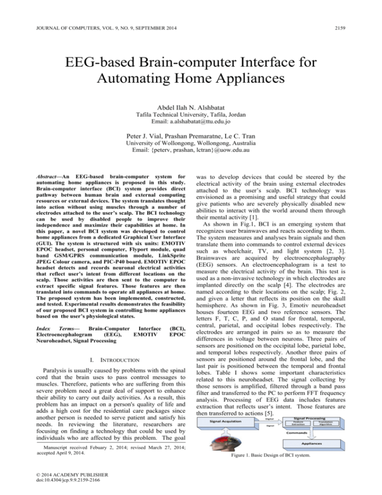
As shown in Fig.1, BCI is an emerging system that
recognizes user brainwaves and reacts according to them.
The system measures and analyses brain signals and then
translate them into commands to control external devices
such as wheelchair, TV, and light system [2, 3].
Brainwaves are acquired by electroencephalography
(EEG) sensors. An electroencephalogram is a test to
measure the electrical activity of the brain. This test is
used as a non-invasive technology in which electrodes are
implanted directly on the scalp [4]. The electrodes are
named according to their locations on the scalp; Fig. 2,
and given a letter that reflects its position on the skull
hemisphere. As shown in Fig. 3, Emotiv neuroheadset
houses fourteen EEG and two reference sensors. The
letters F, T, C, P, and O stand for frontal, temporal,
central, parietal, and occipital lobes respectively. The
electrodes are arranged in pairs so as to measure the
differences in voltage between neurons. Three pairs of
sensors are positioned on the occipital lobe, parietal lobe,
and temporal lobes respectively. Another three pairs of
sensors are positioned around the frontal lobe, and the
last pair is positioned between the temporal and frontal
lobes. Table I shows some important characteristics
related to this neuroheadset. The signal collecting by
those sensors is amplified, filtered through a band pass
filter and transferred to the PC to perform FFT frequency
analysis. Processing of EEG data includes features
extraction that reflects user’s intent. Those features are
then transferred to actions [5].
Figure 1. Basic Design of BCI system.
2160
JOURNAL OF COMPUTERS, VOL. 9, NO. 9, SEPTEMBER 2014
Figure 2. Adult human brain is divided into four lobes: frontal,
temporal, parietal, and occipital lobe
13–30 Hz and is associated with alertness, intention,
concentration, problem solving, judgment, decision
making, and motor activities. This rhythm can be found
in the frontal and parietal region. Gamma rhythm has the
frequency range of 30–42 Hz and is associated with
certain motor functions, high energy states such as when
we are afraid or when we are concentrating on a complex
task [6].
In this paper, we aim to help owners of physical
disabilities in improving their life quality and be able to
open and close doors, switch on and switch off the light,
control the television, use the mobile phone, send
massages to people in their community, and operate a
video camera at the home entrance. To satisfy this goal,
we develop a real-time wireless EEG-based BCI system.
The remainder of this paper is organized as follows:
Section 2 presents a brief survey of the related work. In
section 3, we explain the system architecture, hardware
and software design. In section 4, experiments were
performed and results are explained. Finally, we conclude
and discuss future work in section 5.
II.
Figure 3. Location of the fourteen channels by EMOTIV EPOC.
TABLE I:
CHARACTERISTICS OF EMOTIV EEG NEUROHEADSET.
EEG sensors
Reference sensors
Sampling method
Sampling rate
Bandwidth
Connectivity
Resolution
Battery
AF3, AF4, F3, F4, F7, F8, FC5, FC6,
P7, P8, T7, T8, O1, O2
P3(CMS), P4 (DRL)
Sequential sampling
128 Hz
0.2-45 Hz
2.4 GHz
16 bits
lithium polymer
Brainwaves recorded by EEG sensors are characterized
by amplitude and frequency. Amplitude ranges from 0
up to 100 microvolt’s, while frequencies range from 1Hz
up to 100 Hz. Brainwaves are in general divided into five
categories: Delta, Theta, Alpha, Beta, and Gamma. Delta
rhythm has the frequency range of 1–4 Hz and is
associated with coma and dreamless sleep. This rhythm is
seen frequently in adults, and premature babies. In adults,
it can be found in the frontal region of the brain, while in
premature babies, it can be found in the posterior region
of brain. Theta rhythm has the frequency range of 4–8 Hz
and associated with drowsiness, deep meditation,
emotions, and dream sleep. This rhythm is observed in
young children, adults and can be found in parietal and
occipital region of the brain. Both Delta and Theta
rhythm are categorized as slower brainwaves where the
person can feel tired, slow, sluggish, or dreamy.
Alpha rhythm has the frequency range of 8–13 Hz and
is associated with a relaxed state of mind, and conscious
attention. This rhythm is observed in the period after
waking, and right before sleeping. It can be found in most
people in the awake condition with closed eyes within the
occipital region. Beta rhythm has the frequency range of
© 2014 ACADEMY PUBLISHER
LITERATURE REVIEW
Many environmental control systems were proposed
and applied for people with disability to control their
surroundings [7]. Radio frequency identification and
voice recognition [8] are some of these systems. Those
systems work well for people with motion disability
while they will not work for people with voice or vision
impairment. Other systems using human’s physiological
state were proposed. The author in [9] proposed a BCI
system to help disabled people to input phone numbers.
The system is based on the steady-state visual evoked
potential where twelve buttons are illuminated in front of
the user at different rates. To this end, disabled people
could input a phone number by gazing at those buttons.
Interaction between user’s brain and computer was
achieved through a number of ways: Visual Evoked
Potentials (VEP), Slow Cortical Potentials [10], P300
potentials, N400 potentials, and Sensory Motor Rhythm
(SMR). To this end, VEP refers to the electrical potential
recorded from the visual cortex in response to stimulation
of light [11]; P300 is an event related potential (ERP,
recorded in response to the occurrence of a discrete event,
especially when the subject is actively engaged in the task
of detecting the targets). This signal appears
approximately 300ms after some infrequent stimuli and
typically measured by the electrodes covering the parietal
lobe [12].
Several techniques were used in the previous methods
to extract and classify features form brain signals.
Wavelet-based feature extraction algorithms were
introduced in [13]. Artificial Neural Network (ANN) has
been used by [14] for cortical control of arm prosthetics.
Moreover, Power Spectral Density (PSD) [15], Band
Powers (BP) [16], Adaptive Auto Regressive (AAR) [17],
were also used for feature extractions. A great variety of
classification algorithms was also used to design BCI
systems. Linear Discriminant Analysis [18], Support
Vector Machine (SVM) [19], and Hidden Markov Model
JOURNAL OF COMPUTERS, VOL. 9, NO. 9, SEPTEMBER 2014
2161
[20] are some of those classifiers presented in the
literature.
III.
SYSTEM DESCRIPTION
In this work, we have successfully developed a
wireless portable BCI system to detect and process user
though in a real-time. As shown in Fig. 4, and Fig. 5, the
system is generally divided into two blocks: Transmitter
block and Receiver block. Transmitter block is divided
into six sub-blocks: One Neuroheadset, three wireless
modules, one PC and one converter. On the other side,
one wireless module, two PIC microcontrollers, one GSM
module, and two appliances blocks were dedicated for the
receiving side. Following is a description of the microarchitectural design of each module.
A. System Architecture
As shown in Fig. 4, EEG raw signal from the user
scalp is collected, amplified, digitized and transmitted
through a Bluetooth module to the personal computer
using EMOTIV EPOC headset. EMOTIV headset
measures EEG signal from 14 locations positioned at:
AF3, AF4, F3, F4, F7, F8, FC5, FC6, P7, P8, T7, T8, O1,
and O2. EmoEngine is an application provided by
EMOTIV to decode, process data and match them to the
trained patterns of the subject. This application provides
three suites including Expressive, Affective, and
Cognitive. Those suites are grouped by a tool called
Control Panel, Fig. 6. A Cognitive suite as shown in Fig.
7 is used in this study where users can train the system to
detect a specific thought. All subjects trained with the
Cognitive suite to control left, right, pull, and push
movements of a virtual cube. Along with this tool comes
EMOTIV Emokey suite, Fig. 8. Emokey is used for
mapping subject thoughts to keyboard input. Those inputs
are then read and sent as a command through a WiFi
module to the receiver block.
Another WiFi module is used as shown in Fig. 5. This
module receives commands from the wireless device and
directs them to the microcontroller. Two PIC16F877
microcontrollers as shown in Fig. 9 are used to process
commands sent by the subjects. The first microcontroller
is used as a command decoder and a driver for some of
hardware appliances like the light system. The second
microcontroller is programmed to control other
appliances and send some text messages once the
physiological state is detected to a predefined user. Text
messaging was implemented by a quad band GSM/GPRS
communication module.
Figure.5 System architecture, receiver block.
Figure 6. Control Panel.
Figure 7. Cognitive Suite.
Figure 8. Emokey Suite.
Figure 4. System architecture, transmitter block.
© 2014 ACADEMY PUBLISHER
2162
JOURNAL OF COMPUTERS, VOL. 9, NO. 9, SEPTEMBER 2014
Figure 9. Circuit diagram of the receiver side.
B. Hardware Components
As shown in Fig. 10, the structure of our system
consists mainly of commercial off-the-shelf components.
Part (a) shows the EMOTIV EPOC headset that is used to
record raw EEG signals and transmits that data to the
computer via a Bluetooth module. The headset has 14
saline sensors to tune into subject’s brain electric signals,
and two axis gyroscope for head movements. It has the
capability to detect a wide range of thoughts and
emotions such as excitement, engagement, meditation,
and frustration. Further, left, right, up, down, push, pull
movements, and facial actions like individual’s smiling,
laughing, clenching, and smirking can be detected. All
the data coming out from the headset is encrypted and
passed to the computer. Emotiv software like (edk.dll) is
used to decrypt this data and makes it available to the
researchers who have an educational license.
Part (b) shows a Flyport module as well as a
USB_UART (Universal Asynchronous ReceiverTransmitter) converter. This converter receives the
commands from the PC through a USB connection,
converts them into a UART, and sends them to the
module. USB_UART converter is based on the FT232RL
chip, while the Flyport is an 802.11 b/g/n WiFi compact
module integrated with a microchip PIC 24FJ256GA106
processor. The Flyport has a 26 pin connector, powered
with a 3.3 or 5V, and embeds with a TCP/IP stack for
controlling the transceiver. It has several analog channels
connected to the 10bit ADC, thus it can read input from
sensors, and control other devices like servo motors and
more. It can provide several services such as: Web server,
TCP Socket, UDP Socket, SMTP Client, and SNTP
Client.
All applications running on Flyport module are written
using an openPicus IDE. TCP/IP stack embedded on this
© 2014 ACADEMY PUBLISHER
module is based mainly on that one from Microchip.
Consequently, openPicus IDE integrates the stack with
the operating system (FreeRTOS) so as to ease the
management of any TCP/IP operation. On that basis, we
created an application using C# to exchange data between
Emotiv Software and USB. Then, another two
applications were created to exchange data between
server and client. As shown in Fig. 11, once the data is
available at the USB port, the server opens a TCP socket
and initializes the UART. Going through the flow chart,
we can see that the server sends the data to the client, and
keeps lessening to the USB port. Following this
mechanism, Fig. 12 shows how the client reads the socket
and writes its contents to the UART. With this technique,
the subject is able to convey his thought to any external
hardware available at his surroundings.
Part (c) shows our system that interfaced to the home
appliances. The system consists of the following: Flyport
module, PIC-P40 board, ADH8066 module, and
LinkSprite JPEG Colour camera. Following is a brief
description for all modules.
PIC-P40 board has a 40 pins PIC microcontrollers
socket, RS232 connector and MAX232 driver. Another
socket was added to the board to hold the second
microcontroller. The microcontroller that has been used
for this project is PIC16F877. Both microcontrollers are
powered by LM317 voltage regulator, and the oscillator
circuit was made with 20 Mhz crystal oscillator. Since the
RS232 is not compatible with the PIC microcontrollers,
the MAX232 was connected to the first microcontroller
using PIC UART Tx (pin number 25) and PIC UART Rx
(pin number 26) to convert TTL level to RS232 level and
vice versa. Likewise pins of port A for both
microcontrollers were connected to 2 LEDs to simulate
some appliances at home.
ADH8066 is a quad band GSM/GPRS communication
module. This module has a SIM holder, RF connector to
be connected with an external antenna, and UART
interface to simplify the connection with the PIC
microcontroller. Moreover, it supports standard AT
commands which provides data communication functions.
In this project, software was written and loaded to the
microcontroller to send AT commands to the module.
The software receives the user thought and commands the
ADH8066 module to send SMS messages to a predefined
number.
LinkSprite JPEG Colour camera is used to capture the
image and send it to the subject. To capture the image
from the camera, a specific command should be sent
using the UART interface. Those commands were
programmed and downloaded to the second
microcontroller. Since the camera communicates at TTL
Level; TXD, RXD, and GND pins of the camera were
connected to the PIC UART pins. Two servo motors were
used to move the camera left, right, up, and down
respectively. A desktop application was written in C# to
receive and present the image in front of the subject. As
soon as the camera captured the image, user thought
would be converted to a command to open the main gate
of the house.
JOURNAL OF COMPUTERS, VOL. 9, NO. 9, SEPTEMBER 2014
2163
TABLE II
ADH8066 FEATURES
Feature
Description
Frequency
850/900/1800/1900 MHz
RF Output Power
2W
Sensitivity
<-106 dBm
Command
AT Command
Power voltage
3.4v-4.5v
Average Current
<2.5mA
SIM
Standard SIM
Protocol
Support GSM/GPRS
RF connector
50 ohm
SMS
Support PDU
Maximum baud rate
115,200 bps
(d)
Figure 10. Demonstration of the practical BCI system, (a) EMOTIV
EPOC neuroheadset, (b) FLYPORT WiFi module, (c) PIC-P40,
ADH8066, and LinkSprite camera, (d) The whole system with the
power unit.
IV.
(a)
(b)
(c)
© 2014 ACADEMY PUBLISHER
EXPERIMENTAL RESULTS
The experiment consists of several runs and each lasts
12 seconds. The data is collected from a healthy male
subject. We used the research edition SDK that includes
an EMOTIV EPOC EEG neuroheadset as shown in Fig.
10 Part (a), EMOTIV EPOC Control Panel as shown in
Fig. 6, EmoComposer as shown in Fig. 13, EmoKey and
TestBench are shown in Fig. 8 and Fig. 14 respectively.
The subject’s task was to use cognitive suite to control
left, right, pull, and push movements of a virtual cube
designed by EMOTIV. The subject was seated in front of
the PC running EMOTIV software and was instructed to
perform the appropriate imagery task to move the virtual
cube to the desired direction. We simulated the
environment with two LEDs to evaluate the opening of
the door and switching the lights in the real world.
Command for controlling the messages were directed to a
real time hardware interface circuit. Control signals for
the modem (ADH8066 module) and LEDs were
dependent on the movement of the virtual cube supplied
by cognitive suite. The Emokey software was used for
mapping the cognitive actions to keyboard input. The
actions push, pull, left, and right were mapped to the keys
(i), (l), (k), and (m) respectively.
The system was connected to the BCI through a clientserver protocol. The system acts as a client while
computer running the BCI software acts as a server. After
every stimulus, the BCI system processes the brain
signals and converts them into a keystroke. We created an
application using C# to exchange data between BCI and
the system via a TCP-IP socket. The code is divided into
two basic parts: listening for a key pressed, and sending
the corresponding commands to the server through the
USB port. Once the keystroke is done, the server sends a
data string of one byte, and the client responds
accordingly. The time interval between the BCI
command and the activity was set at 4.0s. The system
triggered one output each time it received a command
from the BCI. To trigger the activity to the original case,
the system should receive the same command in the
second run, this means that each activity could run in
minimum of 10 seconds. Opening of the door depends on
2164
JOURNAL OF COMPUTERS, VOL. 9, NO. 9, SEPTEMBER 2014
the camera attached to the BCI system. The image of the
camera was transmitted in streaming over a WiFi to the
computer that is placed in front of the user. Any changes
in the image were given a priory in issuing a command to
open the door. The data for the left, right, pull, and push
movements of a virtual cube was collected and shown in
Fig.14. Further analysis were conducted using EEGLAB
and shown in Fig.15.
(a)
Figure 11. Server action while sending subject’s thought.
(b)
Figure 12. Client action while receiving subject’s thought.
(c)
(d)
Figure 14. Real-time EEG Measurements in TestBench: (a) Left, (b)
Right, (c) Pull, (d) Push. The data shown corresponds to the 14 channels
being picked up by the EMOTIV EPOC EEG Neuroheadset.
Figure 13. EmoComposer suite.
© 2014 ACADEMY PUBLISHER
JOURNAL OF COMPUTERS, VOL. 9, NO. 9, SEPTEMBER 2014
2165
V.
(a)
CONCLUSION AND FUTURE WORK
In this study, a real-time EEG-based brain-computer
system was proposed for controlling home appliances.
The system consists mainly of an EMOTIV EPOIC
headset and an embedded module. The embedded module
is based on the PIC16F877 chip and some peripherals.
The prototype allows home appliances to be controlled
successfully through the subject’s brain electrical activity
in real-time performance. EMOTIV EPOC headset was
used to record EEG signal and transmits that data to the
computer via a Bluetooth module. The received EEG data
was processed by the software provided by EMOTIV and
results were transmitted to the embedded system to
control the appliances through a WiFi module. A
Graphical User Interface (GUI) was developed to detect a
key stroke and converted it to a certain command. One
male subject participated in the experiment. We trained
the subject to the cognitive suite to control left, right, pull,
and push movements of a virtual cube. The experimental
results demonstrate the feasibility of our proposed BCI
system in controlling home appliances based on the
user’s physiological states. Moreover, the modular
approach applied in designing this system will give us the
opportunity to configure it for different application
scenarios in future.
REFERENCES
(b)
(c)
(d)
Figure 15. Real-time EEG Measurements in TestBench: (a) Left, (b)
Right, (c) Pull, (d) Push. The data shown are processed using EEGLAB
© 2014 ACADEMY PUBLISHER
[1]
S. G. Mason, M. M. Moore Jackson, and G. E. Birch, “A
general framework for characterizing studies of brain
interface technology,” in Annuls of
Biomedical
Engineering, vol. 33, no II, pp 1653-1670, Nov. 2005.
[2] C. Guger, A. Schlögl, C. Neuper, D. Walterspacher, T.
Strein, and G. Pfurtscheller, “Rapid prototyping of an
EEG-based brain-computer interface (BCI),” IEEE
Transactions on Neural Systems and Rehabilitation
Engineering, vol. 9, no. 1, pp. 49–58, March 2001.
[3] T. M. Vaughan, J. R. Wolpaw, and E. Donchin, “EEGbased communication: Prospects and problems,” IEEE
Transactions on Neural Systems and Rehabilitation
Engineering, vol. 4, no. 4, pp. 425–430, Dec 1996.
[4] K. R. Müller and B. Blankertz, “Toward non-invasive
brain-computer interfaces,” IEEE Signal Processing
Magazine, vol. 128, no. 1, pp. 125-128, 2006.
[5] J. R. Wolpaw, N. Birbaumer, D. J. McFarland, G.
Pfurtscheller, and T. M. Vaughan, “Brain-computer
Interface for Communication and Control,” Clinical
Neurophysiology, vol. 133, pp. 767-791, 2002.
[6] Benbadis, Selim, et al. “Handbook of EEG
Interpretation.” Demos Medical, 2007.
[7] S. Helal, W. Mann, H. E. Zabadani, J. King, Y. Kaddoura,
and E. Jansen, “The gator tech smart house: A
programmable pervasive space,” IEEE Comput. Soc., vol.
38, pp. 50-60, 2005.
[8] C. Yerrapragada and P. S. Fisher, “Voice controlled smart
house,” IEEE Int. Conf. on Consumer Electronics, vol. 1,
pp. 154-155, 1993.
[9] M. Cheng, X. R. Gao, S. K. Gao, and D. F. Xu, “Design
and Implementation of a Brain-computer Interface with
High Transfer Rates,” IEEE Trans. Biomed. Eng., vol. 49,
pp. 1181-1186, 2002.
[10] N. Birbaumer, N. Ghanayim, T. Hinterberger, I. Iversen,
B. Kotchoubey, A. Kübler, J. Perelmouter, E. Taub, and H.
2166
[11]
[12]
[13]
[14]
[15]
[16]
[17]
JOURNAL OF COMPUTERS, VOL. 9, NO. 9, SEPTEMBER 2014
Flor, “A spelling device for the paralysed,” Nature, vol.
398, pp. 297- 298, 1999.
J. R. Wolpaw, N. Birbaumer, G. Pfurtscheller, D. J.
McFarland, and Brain, “Computer interfaces for
communication and control,” Journal of
Clinical
Neurophysiology, vol. 113, pp 529–538 ,2002.
A. Furdea, S. Halder, D. J. Krusienski, D. Bross, F.
Nijboer, N. Birbaumer, and A. Kubler, “An auditory
oddball (P300) spelling system for brain-computer
interfaces,” Psychophysiology, vol. 46, no. 3, pp. 617-625,
2009.
V. Bostanov, “BCI Competition 2003{Data sets IB and
IIB: Feature extraction from event-related brain potentials
with the continuous wavelet transform and the T-value
scalogram,” IEEE Transactions on Biomedical
Engineering, vol. 51, no. 6, pp. 1057-1061, 2004.
A. B. Schwartz, D. M. Taylor, and S. I .Tillery,
“Extraction algorithms for cortical control of arm
prosthetics,” Curr. Opin.Neurobiol, 11 701–7, 2001.
J. R. Mill and J. Mourino, “Asynchronous BCI and local
neural classifiers: An overview of the adaptive brain
interface project,” IEEE Transactions on Neural Systems
and Rehabilitation Engineering, Special Issue on BrainComputer Interface Technology, 2003.
G. Pfurtscheller, C. Neuper, D. Flotzinger, and M.
Pregenzer,
“EEG-based
Discrimination
between
Imagination of Right and Left Hand Movement,”
Electroencephalography and Clinical Neurophysiology,
vol. 103, pp. 642-651, 1997.
G. Pfurtscheller, C. Neuper, A. Schlogl, and K. Lugger,
“Reparability of EEG signals recorded during right and
left motor imagery using adaptive autoregressive
parameters,” IEEE Transactions on Rehabilitation
Engineering, vol. 6, no. 3, 1998.
© 2014 ACADEMY PUBLISHER
[18] S. Bhattacharyya, A. Khasnobish, S. Chatterjee, A. Konar,
and D.N. Tibarewala, “Performance analysis of LDA,
QDA and KNN algorithms in left-right limb movement
classification from EEG data,” in Systems in Medicine and
Biology (ICSMB), 2010, pp. 126 – 131.
[19] Y. Li, C. Guan, H. Li, and Z. Chin, “A self-training Semisupervised SVM Algorithm and its pplication in an EEGbased Brain Computer Interface Speller System,” Pattern
Recognition Letters, vol. 29, no. 9, pp. 1285–1294, 2008.
[20] L. R. Rabiner, “A tutorial on hidden markov models and
selected applications in speech recognition,” in Proc. of
the IEEE, 1989, pp. 257-286.
Abdel Ilah Alshbatat is an academic staff member at Tafila
Technical University in the Electrical Engineering Department,
Faculty of Engineering, Tafila, Jordan.
Peter James Vial is an academic staff member at the University
of Wollongong in the School of Electrical, Computer and
Telecommunications Engineering, in the Faculty of Engineering
and Information Sciences, Wollongong.
Prashan Premaratne is an academic staff member at the
University of Wollongong in the School of Electrical, Computer
and Telecommunications Engineering, in the Faculty of
Engineering and Information Sciences, Wollongong.
Le Chung Tran is an academic staff member at the University
of Wollongong in the School of Electrical, Computer and
Telecommunications Engineering, in the Faculty of Engineering
and Information Sciences, Wollongong.
