EE 105 Informal Lab Report Name: SID: (You don«t have to type
advertisement
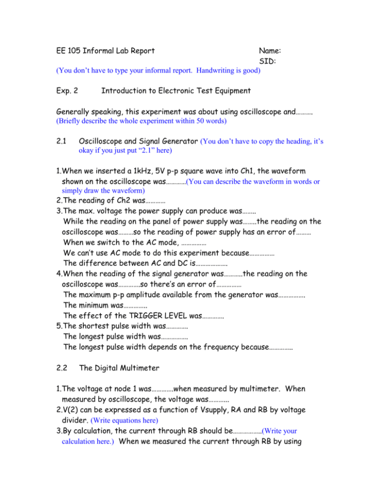
EE 105 Informal Lab Report Name: SID: (You don’t have to type your informal report. Handwriting is good) Exp. 2 Introduction to Electronic Test Equipment Generally speaking, this experiment was about using oscilloscope and………. (Briefly describe the whole experiment within 50 words) 2.1 Oscilloscope and Signal Generator (You don’t have to copy the heading, it’s okay if you just put “2.1” here) 1.When we inserted a 1kHz, 5V p-p square wave into Ch1, the waveform shown on the oscilloscope was…………(You can describe the waveform in words or simply draw the waveform) 2.The reading of Ch2 was………… 3.The max. voltage the power supply can produce was…….. While the reading on the panel of power supply was……..the reading on the oscilloscope was………so the reading of power supply has an error of……… When we switch to the AC mode, …………… We can’t use AC mode to do this experiment because…………… The difference between AC and DC is………………. 4.When the reading of the signal generator was………..the reading on the oscilloscope was………….so there’s an error of…………… The maximum p-p amplitude available from the generator was……………. The minimum was………….. The effect of the TRIGGER LEVEL was…………. 5.The shortest pulse width was…………. The longest pulse width was……………. The longest pulse width depends on the frequency because………….. 2.2 The Digital Multimeter 1.The voltage at node 1 was………….when measured by multimeter. When measured by oscilloscope, the voltage was………... 2.V(2) can be expressed as a function of Vsupply, RA and RB by voltage divider. (Write equations here) 3.By calculation, the current through RB should be……………..(Write your calculation here.) When we measured the current through RB by using multimeter, the result was……………..There’s an error of……………..I think the reason for this error was……… 4.We should never connect an ideal ammeter across a voltage source because……………… 2.3 The HP 4155A/B as a Parameter Analyzer 1.The resistance of this 10k resistor was………..when measured by multimeter. 2.By using the oscilloscope and multimeter, we got the I-V plot for this resistor as following. (Put your I-V plot here, there should be two lines and they should be labeled “using oscilloscope” and “using DMM”, respectively. Or you may want to put two lines in two different graphs if they are very close to each other. You can also put a table here contenting your measured values.) 3.See attachment for the I-V plot obtained by using HP-4155. 5.From the slope, we can find that the resistance was……………. (Put your calculation here) 7.(Simply compare the results obtained by using different test equipments.) 2.5 Transient Analysis (Draw the circuit here because you need the values of R and C to explain your graphs.) 3.(Sketch the 8 waveforms (inputs and outputs of 1kHz, 100Hz, 10kHz, and 100kHz) here. You can put input and output in the same graph for each frequency. Then there should be total 4 graphs. Remember to label all the relevant points.) 4.The transient response of this RC circuit can be explained by the firstorder RC delay. (You should derive or at least write down the equation for firstorder RC delay here and use it to explain your graphs.) Conclusion (Put a conclusion within 100 words for the whole report here.) Please note that this is only an example. There’s no fixed style for informal reports. But you should always remember to (1) do error analysis or comparison between theoretical value and measured result. (2) answer questions asked in the lab manual.
