ABAQUS Tutorial – Column Buckling
Consider a 5 m column with a 10 cm circular cross-section (R=.05m) loaded in axial
compression. The column is pinned at its ends. Determine the critical buckling modes and
corresponding mode shapes
Theoretical Solution
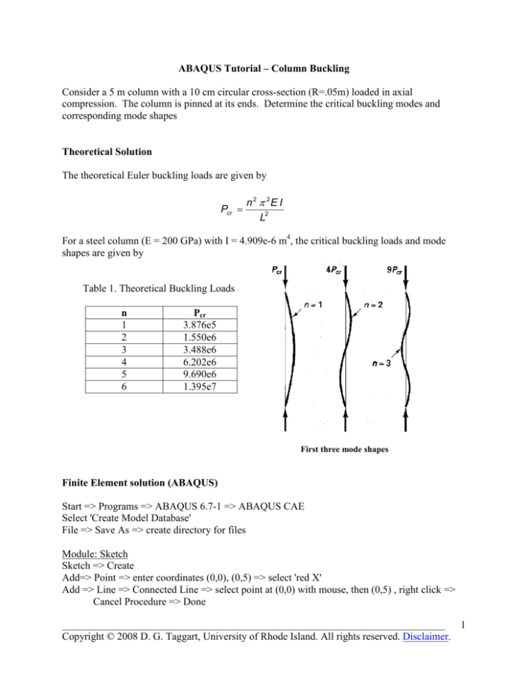
The theoretical Euler buckling loads are given by
Pcr =
n 2 π 2E I
L2
For a steel column (E = 200 GPa) with I = 4.909e-6 m4, the critical buckling loads and mode
shapes are given by
Table 1. Theoretical Buckling Loads
n
1
2
3
4
5
6
Pcr
3.876e5
1.550e6
3.488e6
6.202e6
9.690e6
1.395e7
First three mode shapes
Finite Element solution (ABAQUS)
Start => Programs => ABAQUS 6.7-1 => ABAQUS CAE
Select 'Create Model Database'
File => Save As => create directory for files
Module: Sketch
Sketch => Create
Add=> Point => enter coordinates (0,0), (0,5) => select 'red X'
Add => Line => Connected Line => select point at (0,0) with mouse, then (0,5) , right click =>
Cancel Procedure => Done
__________________________________________________________________________
1
Copyright © 2008 D. G. Taggart, University of Rhode Island. All rights reserved. Disclaimer.
Module: Part
Part => Create => select 2D Planar, Deformable, Wire, Approx size 10 => Continue
Add => Sketch => select 'Sketch-1' => Done => Done
Module: Property
Material => Create => Name: Material-1, Mechanical, Elasticity, Elastic => set Young's
modulus = 200e9, Poisson's ratio = 0.3 => OK
Profile => Create => Circular => r=.05 => OK
Section => Create => Name: Section-1, Beam, Beam => Continue => Profile Name: Profile-1
=> Linear Properties => E=200e9, G=77e9 => OK => OK
Assign Section => select all elements by dragging mouse => Done => Section-1 => Done
Assign Beam Section Orientation => select full model => Done => n1 direction = 0.0,0.0,-1.0 =>
Done
Module: Assembly
Instance => Create => Part-1 => OK
Module: Step
Step => Create => Name: Step-1, Linear Perturbation, Buckle => Continue => Number of
Eigenvalues requested: 6 => OK
Module: Load
Load => Create => Name: Step-1, Step: Step 1, Mechanical, Concentrated Force => Continue =>
select point at (0,5) => Done => set CF 1 =0, CF 2 = -1 => OK
BC => Create => Name: BC-1, Step: Step-1, Mechanical, Displacement/Rotation => Continue
=> select point at (0,0) => Done => U1=U2=0
BC => Create => Name: BC-1, Step: Step-1, Mechanical, Displacement/Rotation => Continue
=> select point at (0,5) => Done => U2=0
Module: Mesh
Seed => Edge by Size => select full model by dragging mouse => Done => Element Size=.25 =>
press Enter => Done
Mesh => Element Type => select full model by dragging mouse => Done => Element Library:
Standard, Geometric Order: Linear, Family: Beam, Cubic interpolation (B23)=> OK =>
Done
Mesh => Instance => OK to mesh the part Instance: Yes => Done
Module: Job
Job => Create => Name: Job-1, Model: Model-1 => Continue => Job Type: Full analysis, Run
Mode: Background, Submit Time: Immediately => OK
Job => Manager => Submit => Job-1
Results
__________________________________________________________________________
2
Copyright © 2008 D. G. Taggart, University of Rhode Island. All rights reserved. Disclaimer.
Module: Visualization
Result => Step.Frame => view Eigenvalues (Buckling Loads) - see Table 2 below
Plot => Deformed Shape
View => Graphics Options => Background Color => White
Ctrl-C to copy viewport to clipboard => Open MS Word Document => Ctrl-V to paste image
Plot=> Contours => Result => Field Output => select S, Max. Principal => Section Points =>
Category: 'beam general' => select section points at +/- 2.5 to view stress contours.
Ctrl-C to copy viewport to clipboard => Open MS Word Document => Ctrl-V to paste image
Report => Field Output => Setup => Number of Significant Digits => 6
Report => Field Output => Variable => Position: Unique Nodal => select U: Spatial
Displacements, UR3: Rotational Displacements, S: Max. Principal => Apply
Cut and paste tabulated results from 'abaqus.rpt' file to MS Word document.
Table 2. Buckling Loads (FEA)
__________________________________________________________________________
3
Copyright © 2008 D. G. Taggart, University of Rhode Island. All rights reserved. Disclaimer.
Buckled Mode Shapes:
__________________________________________________________________________
4
Copyright © 2008 D. G. Taggart, University of Rhode Island. All rights reserved. Disclaimer.


