Packet Tracer - Explore a Network
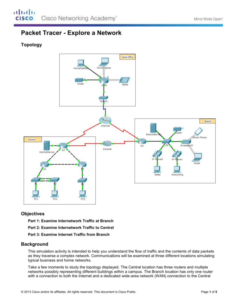
Topology
Objectives
Part 1: Examine Internetwork Traffic at Branch
Part 2: Examine Internetwork Traffic to Central
Part 3: Examine Internet Traffic from Branch
Background
This simulation activity is intended to help you understand the flow of traffic and the contents of data packets
as they traverse a complex network. Communications will be examined at three different locations simulating
typical business and home networks.
Take a few moments to study the topology displayed. The Central location has three routers and multiple
networks possibly representing different buildings within a campus. The Branch location has only one router
with a connection to both the Internet and a dedicated wide-area network (WAN) connection to the Central
© 2013 Cisco and/or its affiliates. All rights reserved. This document is Cisco Public.
Page 1 of 5
Packet Tracer - Explore a Network
location. The Home Office makes use of a cable modem broadband connection to provide access to both the
Internet and to corporate resources over the Internet.
The devices at each location use a combination of static and dynamic addressing. The devices are configured
with default gateways and Domain Name System (DNS) information, as appropriate.
Part 1: Examine Internetwork Traffic at Branch
In Part 1 of this activity, you will use Simulation mode to generate web traffic and examine the HTTP protocol
along with other protocols necessary for communications.
Step 1: Switching from Realtime to Simulation mode.
a. Click the Simulation mode icon to switch from Realtime mode to Simulation mode.
b. Verify that ARP, DNS, HTTP, and TCP are selected from the Event List Filters.
c.
Move the slider located below the Play Controls buttons (Back, Auto Capture/Play, Capture/Forward)
all the way to the right.
Step 2: Generate traffic using a web browser.
Currently the Simulation Panel is empty. In the Event List at the top of the Simulation Panel there are six
columns listed across the heading. As traffic is generated and stepped through, events display in the list. The
Info column is used to inspect the contents of a particular event.
Note: The panel to the left of the Simulation Panel displays the topology. Use the scrollbars to bring the
Branch location into the panel, if necessary. The panels can be adjusted in size by hovering next to the
scrollbar and dragging left or right.
a. Click the Sales PC in the far left pane.
b. Click the Desktop tab and click the Web Browser icon to open it.
c.
In the URL field, enter http://branchserver.pt.pta and click Go. Look in the Event List in the Simulation
Panel. What is the first type of event listed?
d. Click the DNS info box. In the Out Layers, DNS is listed for Layer 7. Layer 4 is using UDP to contact the
DNS server on port 53 (Dst Port:). Both the source and destination IP addresses are listed. What
information is missing to communicate with the DNS server?
e. Click Auto Capture/Play. In approximately 30 to 40 seconds, a window displays, indicating the
completion of the current simulation. (Or a window may display indicating that the buffer is full.) Click the
View Previous Events button. Scroll back to the top of the list and note the number of ARP events.
Looking at the Device column in Event list, how many of the devices in the Branch location does the ARP
request pass through?
f.
Scroll down the events in the list to the series of DNS events. Select the DNS event that has the “At
Device” listed as BranchServer. Click the square box in the Info column. What can be determined by
selecting Layer 7 in the OSI Model? (Look at the results displayed directly below In Layers.)
g. Click the Outbound PDU Details tab. Scroll to the bottom of the window and locate the DNS Answer
section. What is the address displayed?
© 2013 Cisco and/or its affiliates. All rights reserved. This document is Cisco Public.
Page 2 of 5
Packet Tracer - Explore a Network
h. The next several events are TCP events enabling a communications channel to be established. Select
the last TCP event at device Sales just prior to the HTTP event. Click the colored square Info box to
display the PDU information. Highlight Layer 4 in the In Layers column. Looking at item 6 in the list
directly below the In Layers column, what is the connection state?
i.
The next several events are HTTP events. Select any one of the HTTP events at an intermediary device
(IP Phone or Switch). How many layers are active at one of these devices, and why?
j.
Select the last HTTP event at the Sales PC. Select the uppermost layer from the OSI Model tab. What is
the result listed below the In Layers column?
Part 2: Examine Internetwork Traffic to Central
In Part 2 of this activity, you will use Packet Tracer (PT) Simulation mode to view and examine how traffic
leaving the local network is handled.
Step 1: Set up for traffic capture to the Central web server.
a. Close any open PDU Information windows.
b. Click Reset Simulation (located near the middle of the Simulation Panel).
c.
Type http://centralserver.pt.pta in the web browser of the Sales PC.
d. Click Auto Capture/Play; in approximately 75 seconds, a window displays, indicating the completion of
the current simulation. Click View Previous Events. Scroll back to the top of the list; note that the first
series of events are DNS and there are no ARP entries prior to contacting the BranchServer. Based on
what you have learned so far, why is this the case?
e. Click the last DNS event in the Info column. Select Layer 7 in the OSI Model tab.
By looking at the information provided, what can be determined about the DNS results?
f.
Click the Inbound PDU Details tab. Scroll down to the DNS ANSWER section. What is the address listed
for centralserver.pt.pta?
g. The next several events are ARP events. Click the colored square Info box of the last ARP event. Click
the Inbound PDU Details tab and note the MAC address. Based on the information in the ARP section,
what device is providing the ARP reply?
h. The next several events are TCP events, once again preparing to set up a communications channel. Find
the first HTTP event in the Event List. Click the colored square box of the HTTP event. Highlight Layer 2
in the OSI Model tab. What can be determined about the destination MAC address?
i.
Click the HTTP event at device R4. Notice that Layer 2 contains an Ethernet II header. Click the HTTP
event at device Intranet. What is the Layer 2 listed at this device?
© 2013 Cisco and/or its affiliates. All rights reserved. This document is Cisco Public.
Page 3 of 5
Packet Tracer - Explore a Network
Notice that there are only two active layers, as opposed to three active layers when moving through the
router. This is a WAN connection, which will be discussed in a later course.
Part 3: Examine Internet Traffic from Branch
In Part 3 of this activity, you will clear the events and start a new web request that will make use of the
Internet.
Step 1: Set up for traffic capture to an Internet web server.
a. Close any open PDU information windows.
b. Click Reset Simulation near the middle of the Simulation Panel. Type http://www.netacad.pta in the
web browser of the Sales PC.
c.
Click Auto Capture/Play; in approximately 75 seconds, a window displays, indicating the completion of
the current simulation. Click View Previous Events. Scroll back to the top of the list; notice that the first
series of events are DNS. What do you notice about the number of DNS events?
d. Observe some of the devices that the DNS events travel through on the way to a DNS server. Where are
these devices located?
e. Click the last DNS event. Click the Inbound PDU Details tab and scroll down to the last DNS Answer
section. What is the address listed for www.netacad.pta?
f.
When routers move the HTTP event through the network, there are three layers active in both the In
Layers and Out Layers in the OSI Model tab. Based on that information, how many routers are passed
through?
g. Click the TCP event just prior to the last HTTP event. Based on the information displayed, what is the
purpose of this event?
h. There are several more TCP events listed. Locate the TCP event where the Last Device is IP Phone and
the Device At is Sales. Click the colored square Info box and select Layer 4 in the OSI Model tab. Based
on the information from the output, what is the connection state set to?
© 2013 Cisco and/or its affiliates. All rights reserved. This document is Cisco Public.
Page 4 of 5
Packet Tracer - Explore a Network
Suggested Scoring Rubric
Activity Section
Part 1: Examine
Internetwork Traffic at
Branch
Question
Location
Possible
Points
Step 2c
5
Step 2d
5
Step 2e
5
Step 2f
5
Step 2g
5
Step 2h
5
Step 2i
5
Step 2j
5
Part 1 Total
Part 2: Examine
Internetwork Traffic to
Central
Part 3: Examine Internet
Traffic from Branch
40
Step 1c
5
Step 1d
5
Step 1e
5
Step 1f
5
Step 1g
5
Step 1h
5
Part 2 Total
30
Step 1c
5
Step 1d
5
Step 1e
5
Step 1f
5
Step 1g
5
Step 1h
5
Part 3 Total
30
Total Score
100
© 2013 Cisco and/or its affiliates. All rights reserved. This document is Cisco Public.
Earned
Points
Page 5 of 5

