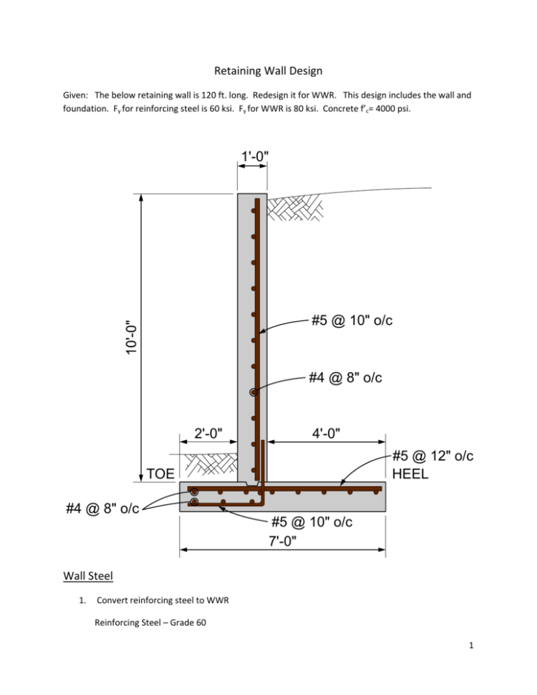
1'-0" #5 @ 10" o/c #4 @ 8" o/c 4'-0" 2'-0" 7'
advertisement

Retaining Wall Design Given: The below retaining wall is 120 ft. long. Redesign it for WWR. This design includes the wall and foundation. Fy for reinforcing steel is 60 ksi. Fy for WWR is 80 ksi. Concrete f’c= 4000 psi. 1'-0" #5 @ 10" o/c #4 @ 8" o/c 2'-0" 4'-0" #5 @ 12" o/c HEEL TOE #4 @ 8" o/c #5 @ 10" o/c 7'-0" Wall Steel 1. Convert reinforcing steel to WWR Reinforcing Steel – Grade 60 1 WWR – Grade 80 Vertical Steel – #5 @10” o/c, As#5 = 0.31 in.2 Asprovided/foot = .31 x 12/10 = 0.372 WWR As = 0.31 x 60000/80000 = 0.2325 in.2 @ 10” spacing, need D23.3 Keep same spacing for overlapping with footer steel. Horizontal steel – #4 @ 8” o/c, As#4 = 0.20 in.2 Asprovided/foot = .20 x 12/8 = 0.30 WWR As = 0.20 x 60000/80000 = 0.0.15 in.2 @ 8” spacing, need D15. Minimum steel requirements, ACI 318 section 14.3 14.3.2 – Vertical reinforcement minimum ratio is 0.0012 14.3.3 – Horizontal reinforcement minimum ratio is 0.0020 Minimum vertical steel = .0012 x 12 x 12 = .173 in.2 < 0.372 Minimum horizontal steel = .0020 x 12 x 12 = 0..289 < 0.30 2. Splicing Requirements Vertical steel is one sheet so no splicing is required. Overlap foundation steel. Horizontal steel is spliced. Calculate ld αβγ 3 ld fy = • • C + K tr 40 λ f ' c db db [ tr= ] A tr fyt 1500 sn Ktr = (0.15*80000)/(1500*10*1) = 0.80 2 Variables Longitudinal Wire D 15 @ 8” db 0.437 in fy 80,000 psi fc 4,000 psi α 1.3 β 1.0 αβ 1.3 γ 0.8 λ 1.0 c 2.0 Ktr 1.24 Atr .15 in2 Fyt 80,000 psi s 10 in n 1 Solving for ld, c + K tr = (2+0.8)/0.437 = 6.41 d b ld = 0.437*(3/40)*(80000/1√4000)* (1.3*0.8*)/6.41 = 6.72” 3 Wire Factor (WF), Greater of : ⎛ fy − 35,000 ⎞ ⎛ 5 db ⎞ ⎜⎜ ⎟⎟ or ⎜ ⎟ ACI 318 12.7.2 f y s ⎝ ⎠ ⎝ ⎠ But not greater than 1. Greater of (80000‐35000)/80000 or (5*.437)/10 = 0.5625 or 0.2185 WF = 0.5625 Splice length = WF* 1.3 * ld = 0.5625 *1.3* 6.72” = 4.9”, minimum is 8” 3. Sheet design Wall length = 120’ * 12 = 1440 in. Less cover at ends(2*3”) = 6 in. 1434 in. Maximum sheet length is 45’ = 540”, therefore try 3 sheets with a splice length of 8”. With three sheets , 2 lap splices needed so the extra length = 2*8” = 16” Total length = 1434 + 16 = 1450” Sheet length = 1450/3 = 483.3” – use 484” = 40’‐4” (sheet length) Wire spacing = 10” , 40’‐4” = 484” 48 spaces @10” = 480” w/ 2” overhangs at each end. Total length in sheets is( 484”*3) = 1452” , extra length = 1452 ‐1450 = 2” for 2 splices So splice length = 8” + (2”/2) = 9” Wall height = 10’*12 = 120” WWR length = 120” – 3”(cover) = 117” 4 Wire spacing = 8” o/c Spaces = 117/8 = 14.6, therefore 14 spaces @ 8” = 112” 117” – 112” = 5” (overhang), Use overhangs of 2” and 3” Sheet designation 10x8 D23.3/D15 117” (+2”, +3”) 40’‐4” (+2”, +2”) 40' - 4" 48 SPACES @ 10" o/c 2" 2" D23.3 D15 Wall Sheet Foundation Steel The foundation is a continuous footer with two layers of reinforcement. The top mat consists of a #5 @ 12” o/c in the 7’ direction and #4 @ 8”o/c in the longitudinal direction or the length of the wall. The bottom mat is located in the toe area and extends into the wall and overlaps the wall steel. 1. Convert to WWR Top Steel #5 @12” o/c, As#5 = 0.31 in.2 5 WWR As = 0.31 x 60000/80000 = 0.2325 in.2 @ 12” spacing, need D23.3 Longitudinal steel – #4 @ 8” o/c, As#4 = 0.20 in.2 Asprovided/foot = .20 x 12/8 = 0.30 WWR As = 0.20 x 60000/80000 = 0.15 in.2 @ 8” spacing, need D15. Bottom Steel #5 @10” o/c, As#5 = 0.31 in.2 WWR As = 0.31 x 60000/80000 = 0.2325 in.2 @ 10” spacing, need D23.3 Longitudinal steel – same as top steel , D15 @ 8” o/c Minimum Steel Requirements ACI 14.3.3 – Horizontal reinforcement ratio is 0.0020 Minimum steel in transverse direction = .0020 *12*12 = 0.289 in2 Asprovided = 0.233(top) + 0.233(12/10) = 0.513 > 0.289 Minimum steel in longitudinal direction = 0.0020 * 12 * (7 *12) = 2.0 in2 Asprovided = 0.15*(78/8) + 0.15 * ((36”‐3’‐2”)/8) = 1.46 + 0.58 = 2.04 > 2.0 – OK 2. Splicing Requirements There are two types of splices , one with the D15 wires running longitudinally and the D23.3 wires. D15 Splice See splice calculations in the wall section for overlap splice. Splice length is 8” D23.3 Splice Calculate ld 6 αβγ 3 ld fy = • • C + K tr 40 λ f ' c db db [ tr= ] A tr fyt 1500 sn Ktr = (0.233*80000)/(1500*10*1) = 1.24 Variables Longitudinal Wire D 23.3 @ 10” db 0.545 in fy 80,000 psi fc 4,000 psi α 1.3 β 1.0 αβ 1.3 γ 0.8 λ 1.0 c 2.0 Ktr 1.24 Atr .233 in2 Fyt 80,000 psi s 10 in n 1 7 Solving for ld, c + K tr = (2+1.24)/0.545 = 5.94 d b ld = 0.545*(3/40)*(80000/1√4000)* (1.3*0.8)/5.94 = 9.0” Wire Factor (WF), Greater of : ⎛ fy − 35,000 ⎞ ⎛ 5 db ⎞ ⎜⎜ ⎟⎟ or ⎜ ⎟ ACI 318 12.7.2 f y s ⎝ ⎠ ⎝ ⎠ But not greater than 1. Greater of (80000‐35000)/80000 or (5*.545)/10 = 0.5625 or 0.27 WF = 0.5625 Splice length = WF* 1.3 * ld = 0.5625 *1.3* 9” = 6.58”, minimum is 8” 3. Sheet Design Top Sheet ‐ D 23.3 @ 12”o/c transverse direction and D15 @ 8” o/c in the longitudinal direction Footer length = 120’ * 12 = 1440 “ Wire length = 1440 – cover (3”+ 3”) = 1434” Sheet length ( max.) = 45’, 1434/12 = 119.5’, use three sheets Splice length of longitudinal wire (D 15) is 8”, so with three sheets there will be two 8” splices. Overall sheet length with splices = 1434 + 8 + 8 = 1450”, divided into 3 sheets Sheet length = 1450/3 = 483.33” , use 484” D23.3 spacing is 12” , spaced over 484”, 484”/12 = 40’‐4” , this is 40 spaces with 2” overhang at each end. D23.3 length = 7’ *12 = 84” – cover(3”+3”) = 78” 8 D 15 @ 8”o/c, sheet width = 78” , no splice in transverse direction. No. of D15 wires, 78”/8 = 9.75 spaces, 9 spaces @ 8” = 72” with 6” left over, or 3” overhangs Top Sheet designation ‐ 12x8 D23.3/D15 78” (+3”, +3”) 40’‐4” (+2”, +2”) 40' - 4" 40 SPACES @ 12" o/c 2" 2" D23.3 D15 Bottom Sheet – L shaped sheet that reinforces toe of footer and overlaps wall sheet. Consists of D23.3 @ 10” o/c with 8 “ overlap of wall sheet and D15 @ 8” o/c that runs longitudinally. 1'-0" 2'-0" 3" 8" 17" 9" 1'-0" 3" COVER 3" 31" 9 17” D23.3 D15 @ 8” o/c 31” Splicing of D15 is the same as top sheet. 3” 2 Spaces @ 7” Since this is a bent sheet there are a couple fabrication rules that apply. One is the maximum sheet length for a bending machine is around 20 ft. The other is the minimum distance from a bend to a wire is 2”, particularly when the wires are on the inside of the bend as in this sheet. The reason is the mandrels need clearance space. Therefore with this requirement the sheet cross‐section will look like the below. 4 Spaces @ 7” 3” With the sheet length limited to 20’, there will be 6 sheets and five splice locations. For the D15 wire the splice length is 8”. 10 Overall Sheet length = 1434 + (5*8”) = 1474” Individual sheet length = 1474”/6 = 245.67” , Use 246” = 20’‐6” D23.3 spacing is 10” o/c. 246/10 = 24.6 spaces. 24 * 10” = 240” with 6” for overhangs, or 3” overhangs on each end. Bottom sheet designation ‐ 10x8 D23.3/D15 48” (0,0) 24’‐6” (+3”, +3”) 20' - 6" 24 SPACES @ 10" o/c 2 @ 7" 3" 31" D23.3 BEND LINE 6" 4 Spaces @ 7" 3" 17" D15 Bottom Sheet Design 11


