Theoretical and Experimental Study of Temperature
advertisement

Theoretical and Experimental Study of Temperature-Dependent
Spectral Properties of Multi-Layer Metal-Dielectric Nano-Film
Structures
Victor N. Boriskin1, Senior Member, IEEE, Mykola I. Ayzatsky1,
Svetlana V. Boriskina2, Senior Member, IEEE, Yuri P. Machehin3, and Alexander Semenov4
1
National Scientific Center “Kharkov Institute of Physics and Technology”, Kharkov, 61108, Ukraine
Tel: (380) 57 3356334, e-mail: boriskin@kipt.kharkov.ua
2
School of Radiophysics, V. Karazin Kharkov National University, Kharkov 61077, Ukraine
Fax: (1) 831 3087657, e-mail: SBoriskina@gmail.com
3
Kharkov National University of Radio Electronics, Kharkov, 61166, Ukraine
4
Institute for Single Crystals NASU, Kharkov, Ukraine
ABSTRACT
We investigate theoretically and experimentally frequency-selective transmission and reflection characteristics
of thin-film metal-dielectric multi-layer structures. The thin-film structures were deposited on glass substrates
using a thermal evaporation technique, and their optical characteristics were studied in the visible and infrared
frequency bands. A computational scheme based on a reiterative method for the calculation of reflection from a
multi-layer stack is developed to model interference filters, polarization splitters and surface-plasmon sensors
and also to study the effect of temperature change on the device characteristics. The temperature dependence is
introduced in the model by taking into account the thermo-optic effect in the dielectrics and contributions from
the phonon–electron and electron–electron scattering in metal layers. Detailed analysis of reflectance
characteristics of thin-film stacks of various material compositions has been performed with the aim to estimate
their temperature sensitivity, to achieve improved device performance and to design sensors and tunable filters.
Keywords: thin film filters, optics of metals, surface plasmon resonance, thermal effects, thermo-optic tuning.
1. INTRODUCTION
Functional optical devices based on multi-layer thin-film structures range from simple one-layer anti-reflection
coatings to narrow-band interference filters to laser mirrors and surface-plasmon resonance biosensors [1, 2].
For many practical applications (e.g. for designing devices for use in adverse temperature environments or
mirrors for high-power lasers) it is necessary to estimate temperature sensitivity of optical characteristics of
multi-layer stacks. Temperature variations cause change of the layers permittivities and thicknesses and thus
affect reflection and transmission characteristics of the structure. A combination of these effects may result in
the temperature-induced instability of the performance of thin-film interference filters or sensors, which may be
compensated by alternating layers of materials with positive and negative thermo-optic coefficients [3]. On the
other hand, multi-layer structures composed of materials with large thermo-optic coefficients may find use in the
development of thermo-optically tunable and switchable thin-film filters and temperature sensors [4].
2. THEORETICAL MODELING OF OPTICAL CHARACTERISTICS OF THIN FILM STACKS
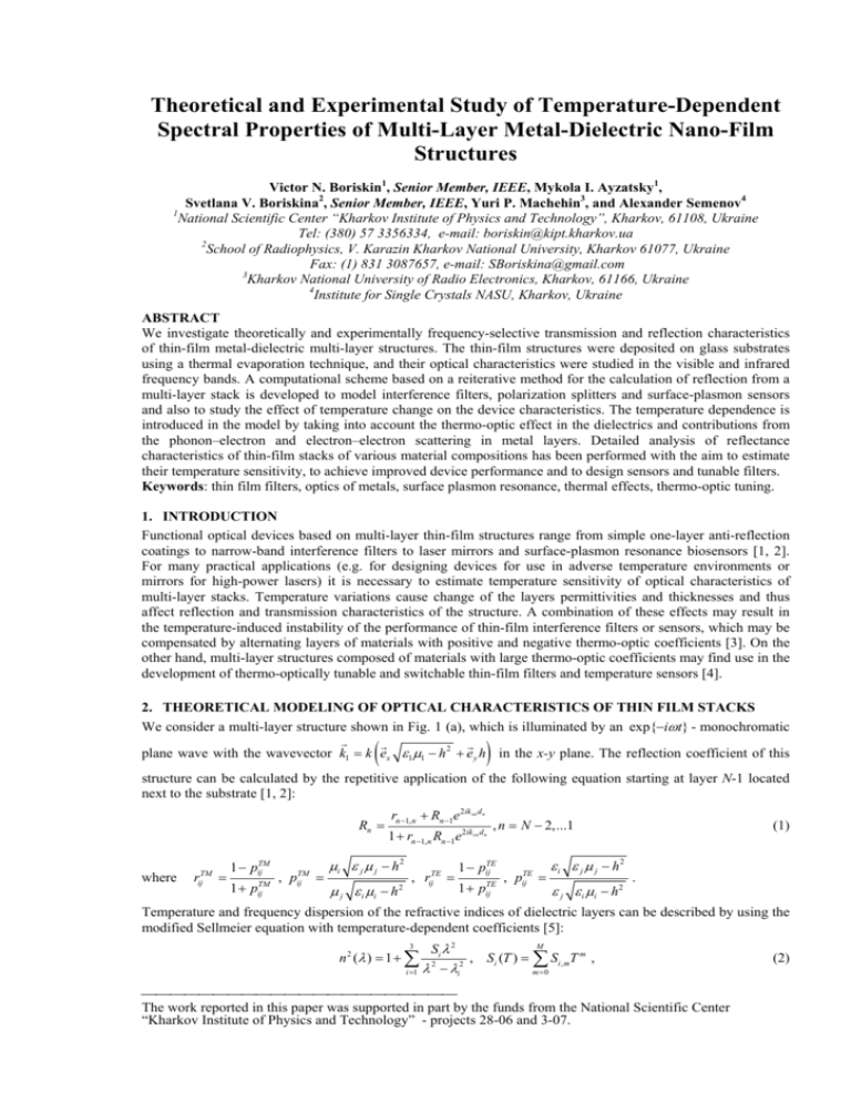
We consider a multi-layer structure shown in Fig. 1 (a), which is illuminated by an exp{−iωt} - monochromatic
G
G
G
plane wave with the wavevector k1 = k ex ε1 μ1 − h 2 + e y h in the x-y plane. The reflection coefficient of this
)
(
structure can be calculated by the repetitive application of the following equation starting at layer N-1 located
next to the substrate [1, 2]:
Rn =
where
rijTM =
1 − pijTM
1 + pijTM
, pijTM =
rn −1, n + Rn −1e 2ik xn dn
1 + rn −1, n Rn −1e 2ik
μi ε j μ j − h 2
μ j ε i μi − h 2
, rijTE =
xn d n
, n = N − 2,...1
1 − pijTE
1 + pijTE
, pijTE =
ε i ε j μ j − h2
ε j ε i μi − h 2
(1)
.
Temperature and frequency dispersion of the refractive indices of dielectric layers can be described by using the
modified Sellmeier equation with temperature-dependent coefficients [5]:
3
n 2 (λ ) = 1 + ∑
i =1
M
Si λ 2
, Si (T ) = ∑ Si , mT m ,
2
2
λ − λi
m=0
⎯⎯⎯⎯⎯⎯⎯⎯⎯⎯⎯⎯⎯⎯⎯⎯⎯⎯⎯⎯⎯⎯
The work reported in this paper was supported in part by the funds from the National Scientific Center
“Kharkov Institute of Physics and Technology” - projects 28-06 and 3-07.
(2)
where Si and λi are the strength and the wavelength location of the absorptive resonances in the material,
respectively. In most cases, the Sellmeier model provides accurate description of the refractive index dispersion
if only three terms in the summation (2) are taken into account: two of them (located in the ultraviolet part of the
spectrum) represent electron transition absorption and the third one (in the infrared) represents the lattice
vibration absorption [5]. The complex frequency-dependent permittivity of metal layers can be described by
using the classical Drude model [6]:
ε = ε∞ −
ω p2
.
ω (ω + iωτ )
(3)
Here, ε ∞ is the relative dielectric constant at high frequencies, ω p and ωτ are the plasma frequency and the
collision frequency, respectively, ω is the angular frequency (e.g., for silver (Ag), ω p (2π ) = 2175 THz and
ωτ (2π ) = 4.35 THz ) [6]. Both, plasma frequency and collision frequency vary with temperature [7]. The
temperature variation of the plasma frequency owing to volumetric effects can be written as follows:
ω p (T ) = ω p 0 (1 + α (T − T0 ) )
−1 2
,
(4)
where α is the expansion coefficient of the metal and T0 is the reference temperature (usually taken as the
room temperature). The temperature dependence of the collision frequency can be attributed to a combination of
two factors: phonon–electron scattering and electron–electron scattering:
ωτ (T ) = ωτ p (T ) + ωτ e (T ) .
(5)
The phonon-electron scattering contribution ωτ p can be described by using the Holstein model:
⎛2
⎛T ⎞
⎟
⎝ TD ⎠
ωτ p (T ) = ω0 ⎜ + 4 ⎜
⎜5
⎝
5T T
D
∫
0
z 4 dz ⎞
⎟,
ez −1 ⎟
⎠
(6)
where TD is the Debye temperature of the metal. The electron–electron scattering frequency ωτ e dispersion can
be taken into account by the model proposed by Lawrence as follows:
ωτ e (T ) =
π 4 ΓΔ ⎛
⎜ ( k BT )
6 hEF ⎜⎝
2
2
⎛ hω ⎞ ⎞
+⎜ 2 ⎟ ⎟.
⎝ 4π ⎠ ⎟⎠
(7)
The model parameters for silver and gold used in numerical simulations were taken from Ref. 7.
1.0
1.0
o
45 TE
θi
ε 2 , μ2 , d 2
ε N −1 , μ N −1 , d N −1
dAg=80nm
0.6
0.4
o
30 TE
0.2
(a)
0.0
400
0.6
0.4
0.2
o
ε N , μN , d N
dAg=150nm
0.8
Reflectivity
ε1 , μ1 , d1
0.8
Transmission
Incident field
45 TM
o
30 TM
dAg=55nm
no Ag layer
0.0
500
600
Wavelength, λ (nm)
700
o
o
o
o
o
0
20
40
60
80
Angle of plane wave incidence
(b)
(c)
Figure 1. (a) Schematic of a multi-layer thin-film stack.
(b) Transmission performance of MacNeille beam splitter for two polarizations and two incident angles: 45 and
30 degree (the structure composition: Schott SF7 glass, d1(ZnS) = 63 nm, d2(MgF2) = 177 nm, d3(ZnS) = 63
nm, d4(MgF2) = 177 nm, d5(ZnS) = 63 nm, d6(MgF2) = 177 nm, d7(ZnS) = 63 nm, Schott SF7 substrate).
(c) Reflectance as a function of the angle of incidence for a surface plasmon resonance sensor based on the
Kretschmann configuration: Schott SF11 glass - Ag layer – water [2].
We test the developed theoretical model and software by comparing the numerical results with those either
obtained by using commercial software packages or available in the literature. As the first example, we consider
a MacNeille polarizing beam splitter, which can be used for the separation of unpolarized light into two
orthogonal linear polarizations (Fig. 1 (b)). As can be seen from Fig. 1 (b), polarization separation functionality
can be achieved at the angle of 45 degrees. These data are in excellent agreement with the results obtained by
using the TracePro® software developed by Lambda Research Corporation [8]. As the second example we
consider a three-layer Kretschmann-type structure for excitation of surface plasmon waves, which is composed
of a silver layer sandwiched between Schott SF11 glass and water (Fig. 1 (c)). The curves in Fig. 1 (c) show the
reflectance of the structure for several thicknesses of the silver film. The sharp minimum in the reflectivity curve
corresponds to the excitation of the surface plasmon wave on the metal layer. This dip disappears for the case of
SF11 glass - water structure (no Ag layer) or if the Ag film is too thick, in which case the structure reduces to
the SF11 glass - Ag system. These results agree well with those obtained in Ref. 2.
3.
FABRICATION, CHARACTERIZATION AND NUMERICAL DESIGN OF TEMPERATURESENSITIVE METAL-DIELECTRIC ZnS/MgF2/Ag STRUCTURES
The multilayer structures under investigation are composed of zinc sulfide (ZnS) layers alternated by
magnesium fluoride (MgF2) layers grown on top of a single Ag layer and a glass substrate, and are designed for
use in the visible and infrared regions of the spectrum. Samples were prepared by thermal evaporation technique
with in-situ ellipsometry used to control the growth process, and their reflection characteristics were measured
as a function of the illumination angle for both p- and s-polarized light excitation. The source of monochromatic
light was a He–Ne laser of wavelength 6328 Å.
o
o
experiment - T=13 C
1.0
theory - T=13 C
1.0
0.8
0.6
Reflectivity
Reflectivity
0.8
TE(p)
0.4
0.6
TM(s)
0.4
Dashed lines:
MgF2/ZnS/Ag/SiO2
TM(s)
0.2
TE(p)
0.2 Solid lines:
MgF2/ZnS/Ag2S/Ag/SiO2
0.0
o
o
o
o
o
o
o
o
o
10 20 30 40 50 60 70 80 90
Angle of plane wave incidence (degree)
0.0
o
o
o
o
o
o
o
o
o
10 20 30 40 50 60 70 80 90
Angle of plane wave incidence (degree)
(a)
(b)
TM(s)-polarization
TM(s)-polarization
TE(p)-polarization
0
0.8
Wavelength, λ (nm)
Reflectivity
700
0.6
0.4
0.2
o
T=40 C
o
T=13 C
0.0
o
o
o
o
o
o
o
o
55 56 57 58 59 60 61 62
Angle of plane wave incidence (degree)
0.2
650
600
0.4
550
0.6
500
0.8
450
0
20 40 60 80 0 20 40 60 80
Illumination angle
Illumination angle
1.0
(c)
(d)
Figure 2. (a) Experimental and (b) calculated reflection coefficients for both polarizations as a function the
angle of incidence (the structure composition: Air , d1(ZnS) = 53 nm, d2(MgF2) = 216 nm, d3(ZnS) = 64 nm,
d4(MgF2) = 164 nm, d5(ZnS) = 33 nm, d6(MgF2) = 263 nm, d7(ZnS) = 24 nm, d8(Ag2S) = 3 nm, d9(Ag) = 400
nm, glass substrate); (c) Shift of the dip in the TM-reflectivity curve caused by the change of temperature (linetheory, dots – experiment); (d) Reflectance as a function of wavelength and illumination angle.
A measured reflectance for one of the prepared samples is shown in Fig. 2 (a). The theoretical curves presented
by dashed lines in Fig. 2 (b) were calculated by using the optical constants of the materials as given in [5-7].
Clearly, experimentally observed resonance in the TM-polarization curve is shifted to a larger angle than that
given by the calculated curve. We attribute this shift to the presence of a thin layer of silver sulfide (Ag2S) that
forms on top of the silver layer in the process of ZnS deposition [9]. Introducing the Ag2S layer between Ag and
ZnS into the model (Fig. 2(b), solid lines) we achieve much better agreement with the experiment (optical
constants of silver sulfide have been taken from Refs. 10). Similar discrepancies between measured and
calculated reflection and transmission characteristics of structures containing silver layers have previously been
explained and eliminated by taking into account the presence of thin contamination layers of either silver sulfide
or MgF2/Ag composite cermet [11]. The temperature increase causes changes of the refractive indices and
thicknesses of all the layers in the stack, and as a result shifts the minimum in the reflectance curve (Fig. 2 (c)).
The minimum shifts to smaller angles owing to the large negative value of the thermo-optic coefficient of Ag2S.
This effect offers possibilities to create temperature-sensitive and thermally-tunable filters and sensor devices.
Finally, polarization-independent device operation can be achieved if the structure geometrical parameters as
well as the operational frequency are adjusted so that the dips in the reflectance curves for both polarizations at
the given wavelength coincide (see Fig. 2 (d)).
4. CONCLUSIONS
In summary, a generalized theoretical approach has been developed to model reflection and transmission
characteristics of metal-dielectric multi-layer thin-film structures. A comprehensive theoretical and experimental
study of temperature-dependent spectral properties of ZnS/MgF2/Ag2S/Ag thin-film stacks has been performed.
Large temperature-induced shifts of angular position of the minima in reflectivity curves of thin-film stacks have
been observed. These observations pave the way for designing temperature-sensitive and thermally tunable and
switchable optical elements.
ACKNOWLEDGEMENTS
S.V.B. is grateful to William Tropf (Johns Hopkins University) and Gary Hawkins (University of Reading) for
useful advice.
REFERENCES
[1] P. H. Lissberger: Optical applications of dielectric thin films, Rep. Prog. Phys., vol. 33, pp. 197-268, 1970.
[2] P. Lecaruyer, E. Maillart, M. Canva, and J. Rolland: Generalization of the Rouard method to an absorbing
thin-film stack and application to surface plasmon resonance, Appl. Opt. vol. 45, pp. 8419-8423, 2006.
[3] H. Blifford: Factors affecting the performance of commercial interference filters, Appl. Opt. vol. 5, pp.
105-111, 1966; B. Li, S.Y. Zhang, J.C. Jiang, D.Q. Liu, F.S. Zhang: Recent progress in improving lowtemperature stability of infrared thin-film interference filters, Opt. Express, vol. 13, pp. 6376-6380, 2005.
[4] L. Domash, M. Wu, N. Nemchuk, and E. Ma: Tunable and switchable multiple-cavity thin film filters, J.
Lightwave Technol. vol. 22, no. 1, pp. 126-135, Jan. 2004.
[5] W. J. Tropf: Temperature-dependent refractive index models for BaF2, CaF2, MgF2, SrF2, LiF, NaF, KCl,
ZnS, and ZnSe, Opt. Eng. vol. 34, no. 5, pp. 1369-1373, 1995; G. Hawkins and R. Hunneman: The
temperature-dependent spectral properties of filter substrate materials in the far-infrared (6–40 mkm),
Infrared Physics & Technology, vol. 45, pp. 69–79, 2004.
[6] P. B. Johnson and R. W. Christy: Optical constants of the noble metals, Phys. Rev. B, vol. 6, pp. 4370–
4379, 1972; M. A. Ordal, L. L. Long, R. J. Bell, S. E. Bell, R. R. Bell, Jr., R. W. Alexander, and C. A.
Ward: Optical properties of the metals Al, Co, Cu, Au, Fe, Pb, Ni, Pd, Pt, Ag, Ti, and W in the infrared and
far infrared, Appl. Opt. vol. 22, pp. 1099–1119, 1983.
[7] A. K. Sharma and B. D. Gupta: Influence of temperature on the sensitivity and signal-to-noise ratio of a
fiber-optic surface-plasmon resonance sensor, Appl. Opt. vol. 45, pp. 151-161, 2006.
[8] http://www.lambdares.com
[9] Handbook of Thin Solid Film Technology, Eds. L.I. Massel, R. Glang, McGraw Hill Company, 1970.
[10] J. M. Bennett, J. L. Stanford, and E. J. Ashley: Optical constants of silver sulfide tarnish films, J. Opt. Soc.
Am. vol. 60, no. 2, pp. 224-232, 1970; G. Busch: Early history chemistry of the physics and
semiconductors-from doubts to fact in a hundred years, Eur. J. Phys., vol. 10, pp. 254-264, 1989; M. ElNahass, A. A. M. Farag, E. M. Ibrahim, and S. Abd-El-Rahman: Structural, optical and electrical properties
of thermally evaporated Ag2S thin films, Vacuum, vol. 72, pp. 453–460, 2004.
[11] G. J. Kovacs and G. D. Scott: Optical excitation of surface plasma waves in layered media, Phys. Rev. B,
vol. 16, no. 4, pp. 1297-1311, 1977; P. Lalanne and J. P. Hugonin: Interaction between optical nanoobjects at metallo-dielectric interfaces, Nature Physics, vol. 2, pp. 551-556, 2006.


