Growth Mechanism of Long and Horizontally Aligned Carbon
advertisement
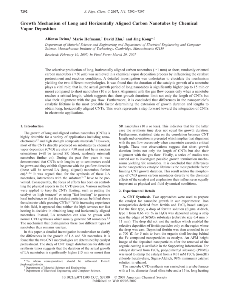
7292 J. Phys. Chem. C 2007, 111, 7292-7297 Growth Mechanism of Long and Horizontally Aligned Carbon Nanotubes by Chemical Vapor Deposition Alfonso Reina,† Mario Hofmann,‡ David Zhu,‡ and Jing Kong*,‡ Department of Material Science and Engineering and Department of Electrical Engineering and Computer Science, Massachusetts Institute of Technology, Cambridge, Massachusetts 02139 ReceiVed: February 10, 2007; In Final Form: March 29, 2007 The selective production of long, horizontally aligned carbon nanotubes (>1 mm) or short, randomly oriented carbon nanotubes (<50 µm) was achieved in a chemical vapor deposition process by influencing the catalyst pretreatment and reaction conditions. A detailed investigation was undertaken to elucidate the mechanism yielding the two different morphologies. It was found that the duration of the catalytic growth of a nanotube plays a vital role; that is, the actual growth period of long nanotubes is significantly higher (up to 15 min or more) compared to short nanotubes (10 s or less). Alignment with the gas flow occurs only when a nanotube reaches a critical length, which suggests that short growth durations limit not only the length of CNTs but also their alignment with the gas flow. Furthermore, it is concluded that differences in the nanoparticle’s catalytic lifetime is the most probable factor determining the extension of growth duration and lengths to obtain long, horizontally aligned CNTs. This work represents a step forward toward the integration of CNTs in electronic applications. 1. Introduction The growth of long and aligned carbon nanotubes (CNTs) is highly desirable for a variety of applications including nanoelectronics1,2 and high strength composite materials.3 However, most of the CNTs directly produced on substrates by chemical vapor deposition (CVD) are short (<50 µm) and lie in random orientations (will be termed SR (short, randomly oriented) nanotubes further on). During the past few years it was demonstrated that CNTs with lengths up to centimeters could be grown and they exhibit alignment with the gas flow direction (these will be termed LA (long, aligned) nanotubes further on).4-14 It was argued that, for the synthesis of these LA nanotubes, interactions with the substrate5-7 have to be prevented. Consequently, the focus of efforts has been on controlling the physical aspects in the CVD process. Various methods were applied to keep the CNTs floating, such as putting the catalyst on high terraces5 or using “fast heating” to generate local turbulence so that the catalyst particles can be lifted above the substrate while growing CNTs.6,7 With increasing experience in this field, it appeared that neither the high terraces nor fast heating is decisive in obtaining long and horizontally aligned nanotubes. Instead, LA nanotubes can also be grown with normal CVD syntheses which usually generate SR nanotubes.8,9 The mechanism that distinguishes these two different types of nanotubes thus remains unclear. In this paper, a detailed investigation is undertaken to clarify the differences in the growth of LA and SR nanotubes. It is found that the two CNT morphologies are determined by catalyst pretreatment. The study of CNT length distributions for different synthesis times suggests that the duration of the actual growth of LA nanotubes is significantly higher (15 min or more) than * To whom correspondence should be addressed. E-mail: jingkong@mit.edu. † Department of Material Science and Engineering. ‡ Department of Electrical Engineering and Computer Science. SR nanotubes (10 s or less). This indicates that for the latter case the synthesis time does not equal the growth duration. Furthermore, statistical data on the correlation between CNT length and orientation is presented which implies that alignment with the gas flow occurs only when a nanotube exceeds a critical length. These two observations suggest that short growth duration limits not only the length of CNTs but also their alignment with the gas flow. Finally, a series of studies was carried out to investigate possible growth termination mechanisms yielding SR nanotubes. It is concluded that differences in the nanoparticles catalytic lifetime is the most probable factor limiting CNT growth duration. This result relates the morphology of CVD grown carbon nanotubes directly to the chemical effects of the catalyst and emphasizes their influence as equally important as physical and fluid dynamical conditions. 2. Experimental Details A. CNT Synthesis. Two approaches were used to prepare the catalyst for nanotube growth in our experiments: Iron nanoparticles derived from ferritin and FeCl3 based catalyst. For the first type, a drop of ferritin solution (Sigma Aldrich, type I from 0.66 vol % in H2O) was deposited along a strip near the edges of Si/SiO2 substrates (substrate size 6.4 mm × 11 mm). The drop did not wet the surface which enabled the selective deposition of ferritin particles only on the region where the drop was cast. Deposited ferritin was then annealed in air at 700 °C for 5 min to burn the organic shell leaving behind the Fe compound nanoparticles as catalyst. An AFM height image of the deposited nanoparticles after the removal of the organic coating is available in the Supporting Information. For catalyst derived from FeCl3, poly(dimethyl siloxane) (PDMS) was used to stamp the catalyst from a 0.01 mM FeCl3 (iron(III) chloride hexahydrate, Sigma-Aldrich, 98% minimum) catalyst solution in ethanol. The nanotube CVD synthesis was carried out in a tube furnace with a 1 in. diameter fused silica tube and a 15 in. long heating 10.1021/jp0711500 CCC: $37.00 © 2007 American Chemical Society Published on Web 05/03/2007 Growth Mechanism of Carbon Nanotubes J. Phys. Chem. C, Vol. 111, No. 20, 2007 7293 Figure 1. SEM images of samples containing short, randomly aligned CNTs (a-c) and samples containing long, gas flow aligned CNTs (d-f) at different magnifications and locations; (a and d) overall view of catalyst region, (b and e) edge of catalyst region, and (c and f) inside catalyst region. Gas flows from right to left. All CNTs shown were grown using ferritin catalyst and ethanol CVD with Ar + H2 (a-c) and Ar + O2 (d-f) gas mixtures during catalyst pretreatment. TABLE 1: Summary of Different Results Regarding CNT Characteristics Obtained with Different Process Parameters (Catalyst, Carbon Source, and Gases during Pregrowth Heating) methane CVD ethanol CVD ferritin Ar + O2 Ar + H2 short, random: variable density long, aligned: variable density (up to 5 mm) FeCl3 Ar + O2 Ar + H2 short, random: high density long, aligned: low density (100 µm - 6 mm) long, aligned: variable density (up to 1 cm) short, random: high density (90% of the growths) + long, aligned: 10% of the growths; variable density (up to 8 mm) long, aligned: low density (<1 mm) short, random: high density (90% of the growths) + long, aligned: 10% of the growths; variable density zone. The process consisted of two steps. First, the substrates were heated from room temperature to growth temperature (900 °C) in a fixed amount of time, a step that will be subsequently referred to as catalyst pretreatment. The effect of pretreatment under different mixtures of gases was investigated using 600 sccm Ar + 10 sccm O2 or 600 sccm Ar + 440 H2. Once the furnace temperature reached 900 °C, for ethanol CVD, a gas flow of 600 sccm Ar (bubbled through ethanol) + 440 sccm H2 was used. For methane CVD, a gas flow of 1000 sccm CH4 + 440 sccm H2 was used. After the synthesis, the furnace was cooled down under the flow of 600 sccm Ar + 440 sccm H2 to room temperature. B. CNT Characterization. Samples were characterized using a JEOL JSM-6060 scanning electron microscope (SEM) and a Dimension 3100 atomic force microscope (AFM). Because of an electron emission contrast of a differently charged SiO2/Si substrate in the vicinity of carbon nanotubes, they could be distinguished in images with magnifications as low as 10X using an acceleration voltage of 1 kV.15 3. Results and Discussions Two types of results-SR nanotubes vs LA nanotubes are obtained respectively by tuning different CVD parameters. Figure 1 shows SEM images representative of the two aforementioned scenarios. These CNTs were synthesized using ferritin-derived nanoparticles under ethanol CVD. Figure 1a-c shows different magnification SEM images of SR nanotubes. These CNTs form a “mat” due to the high density and random orientation. In contrast, Figure 1d-f illustrates samples with LA nanotubes at different magnifications. A sharp contrast in morphology can be noticed from these images. Each result was achieved only by the manipulation of chemical process param- eters, namely the catalyst pretreatment step. A summary of the parameters tested and their results are presented in Table 1. For ethanol CVD, it was found that LA nanotubes grow from both FeCl3 and ferritin derived catalyst if O2 is used during the catalyst pretreatment stage of the process. For methane CVD, the presence of H2 in the pretreatment stage resulted in LA nanotubes from both kinds of catalysts, whereas O2 did not have this effect.16 The significance of these chemical process parameters in the control of nanotube morphology are addressed in the subsequent sections. The results aforementioned were obtained with fused silica tubes that have been used previously for a period of time (generally, 30-50 CVD growths). Processes performed with new fused silica tubes give rise to SR CNTs exclusively. This suggests that a possible conditioning of the tubes is influencing the stability of our experiments. Previous reports have observed a similar influence of the CVD chamber.17 Further efforts are being devoted to improve the understanding of this observation. 3.1. Growth Differences between SR and LA CNTs. Variation of synthesis time was performed for CVD processes resulting in SR and LA CNTs (Figures 2 and 3, respectively). The accurate termination of short time synthesis was achieved by a special flow reversal arrangement that allowed quick displacement of hydrocarbons with an inert gas (see the Supporting Information). Figure 2a indicates that some nanotubes have already grown after 10 s. CNT length distributions do not change significantly over time, and they show a maximum around the same length value for all synthesis times. This observation has two implications. First, it indicates that nanotube growth starts and ends within 10 s or less, and therefore beyond these 10 s, the length of the CNTs is not proportional to growth time as assumed previously.4 Second, 7294 J. Phys. Chem. C, Vol. 111, No. 20, 2007 Reina et al. Figure 2. SEM images of SR nanotubes grown using ferritin catalyst and ethanol CVD with different synthesis times (a-d) and their respective length distributions (e-h); 10 s (a and e), 30 s (b and f), 1 min (c and g), and 15 min (d and h). Gas flows from right to left. Scale bar 20 µm. Figure 3. SEM images of LA nanotubes grown using FeCl3 catalyst and methane CVD with different synthesis times (a-d) and their respective length distributions (e-h); 2 min (a and e), 5 min (b and f), 10 min (c and g), and 15 min (d and h). Gas flows from right to left. Scale bar 1 mm. Figure 4. Statistical data showing the correlation between CNT orientation and length. Orientation is taken as the angle between flow direction and nanotube orientation (a). Map of orientation vs length (b), standard deviation of orientation vs length (c). Data was obtained from CNTs grown with both ethanol and methane CVD. Scale bar 20 µm. as the synthesis time increases, the only feature that is changing is the density of nanotubes, suggesting that particles do not initiate growth of nanotubes at the same time. Figure 3 shows results from experiments with different synthesis times under CVD conditions favoring LA nanotubes and their respective length distributions. From the low magnification images, it can already be inferred qualitatively how the longest nanotubes stemming from the catalyst region tend to get longer as synthesis time increases. Although the peak in the length distribution does not shift significantly with synthesis time, the distribution broadens its longer-length side tail, demonstrating the proportionality between the actual growth duration and the synthesis time for the longest nanotubes. Inside the catalyst region of the LA samples, there are both LA nanotubes and short random orientated nanotubes. This allows us to perform a length vs orientation angle mapping, which is illustrated in Figure 4a. The distribution demonstrates a strong correlation between the degree of alignment and the length of the carbon nanotubes. At short lengths, the standard deviation approaches 52 degrees (Figure 4c), which is in agreement with the value expected for a uniform probability function of the orientation angle (see the Supporting Information). The alignment sets in at a length of 40-50 µm which is illustrated by the narrow angular distribution after this length and confirmed by the standard deviation. This demonstrates that the gas flow effect becomes significant after the growing nanotubes have achieved a critical length. This characteristic is independent of the type of CVD (ethanol or methane) and catalyst (ferritin or FeCl3) used which suggests that it is mainly influenced by fluid dynamics. Growth Mechanism of Carbon Nanotubes J. Phys. Chem. C, Vol. 111, No. 20, 2007 7295 Figure 5. CNTs grown using reduced concentration of ferritin particles, ethanol CVD and catalyst pretreatments favoring short, randomly aligned CNTs (a) and gas-flown aligned CNTs (b). Gas flows from right to left. Scale bar 20 µm. From these last two experimental observations, we find that, in order to obtain LA nanotubes, it is necessary to have extended growth durations and the achievement of a critical length. This implies that the early growth termination of SR CNTs causes both short length and random orientation. Growth termination in the case of SR CNTs can be caused by different reasons which are analyzed in the following sections. 3.2. Causes of CNT Growth Termination. The growth duration is limited by factors that can be divided into mechanical and chemical aspects of CNT growth. For the mechanical aspect, interaction between nanotubes or between nanotubes and the substrate are generally expected to be unfavorable for extended growth duration. These issues are addressed in the following discussion. CNT-CNT Interaction. The high density of SR nanotubes in Figure 1c suggested that possible entanglement may prevent CNTs from continuously growing and thus aligning with gas flow. However, further experimentation demonstrates that the density of nanotubes cannot account for the difference between SR and LA nanotubes. Figure 5 shows SEM pictures of CNTs synthesized from ferritin nanoparticles with 50 times more dilution in concentration than Figure 1. Even with a greatly reduced density of nucleated CNTs, SR and LA nanotubes (Figure 5, panels a and b, respectively) can still be obtained selectively as in the case of Figure 1. In fact, the density of SR nanotubes in Figure 5a is lower than the density of LA nanotubes in Figure 1d-f. This demonstrates that CNT-CNT interaction during growth is not a limitation for length and gas flow alignment in these experiments. CNT-Substrate Interaction. CNT-substrate interactions are usually expected to obstruct CNT growth. For example it is assumed that flow effects could force the nanotubes into contact with the substrate and inhibit growth.8 Our experiments show that synthesis takes place in a macroscopically laminar fluid dynamical condition which is very stable since different sample loading geometries (see the Supporting Information) that are usually expected to change the flow characteristics12 yield the same results. More importantly, selective growth of SR and LA Figure 6. Base growth of SR CNTs grown by methane CVD. AFM images of the same region with Fe nanoparticles before (a) and after CNT growth (b). Scale bar 200 nm. nanotubes can be achieved using the same total gas flow, sample loading geometries and hydrocarbon gas concentration by only changing catalyst pretreatment and conditioning of growth chamber (Table 1). Therefore, gas flow mechanical effects, unlike other reports,5,12 are not the determining parameters leading to LA CNTs in this work. The growth rate of a CNT could also determine if it is susceptible to substrate interaction. For instance, an increased growth rate can have a beneficial influence on a growing CNT since it minimizes the time that the CNT can interact with the substrate under deflection caused, i.e., by thermal vibration or micro turbulences in the gas flow. However, in our experiments, the growth rates of SR CNTs is likely to be of the same order of magnitude or even higher than LA CNTs: A constant growth rate for LA CNTs of approximately 2 µm/s can be assumed from the extension of the length distribution’s tail over time (Figure 3e-h). Similarly, the growth rate of the longest SR nanotubes is at least 1 µm/s, making a growth termination due to significantly lower growth rates unlikely in these experiments. Another aspect of CNT growth relevant in CNT-substrate interactions is the growth mechanism (tip vs base growth). Figure 6 shows the AFM images of the substrate before and after the CVD synthesis of SR nanotubes using ferritin nanoparticles. It can be clearly seen that the SR nanotubes are grown via the “base growth” mechanism, meaning that the catalyst nanoparticle stays attached to the substrate while the nanotube is being extruded. This is consistent with previous findings.18 If a growing CNT is expected to interact with the substrate, a tip growth mechanism could favor the extension of growth duration. In this case, the catalyst particle would move away 7296 J. Phys. Chem. C, Vol. 111, No. 20, 2007 Figure 7. AFM images of two different LA CNT ends suggesting base growth (a and b) and tip growth (c and d); Imaging taken after growth (a and c) and after annealing in air (b and d). CNTs were grown using both ferritin and FeCl3 under ethanol and methane CVD respectively. Scale bar 200 nm. from the substrate while growing a CNT and therefore interactions of any CNT segment with the substrate will not hinder the growth as in the case of base growth. Indeed, previous reports have suggested a tip growth mechanism in the synthesis of LA CNTs.6 We investigated the downstream end part of LA nanotubes after growth as an attempt to clarify if tip growth occurs exclusively in the case of LA nanotubes. Substrates with markers were used to identify the position of the inspected nanotubes. After AFM imaging of the downstream LA CNT ends, the substrate was annealed in air at 450 °C for 30 min to remove a small part of these end sections. Subsequent AFM imaging of the same location clarifies if a catalyst nanoparticle was present at the end of the nanotube. Figure 7 shows two different scenarios observed within the set of nanotubes inspected. Figure 7a-d shows AFM pictures of the end sections of two LA nanotubes. After annealing, the nanotubes start to disappear leaving behind some residues but a catalyst particle is only present in the second case (Figure 7c,d). These results indicate that tip growth is not a necessary condition for growing the LA nanotubes since base growth can also occur. Based on the above discussions, the aforementioned scenarios do not seem to limit CNT growth duration. Therefore growth termination by chemical aspects is favored as presented consequently. Catalyst DeactiVation. The growth duration of CNTs can also be affected by the catalytic lifetime or time between activation and deactivation of the catalyst nanoparticles. It is known that this characteristic time can be affected by CVD process parameters19 which is in agreement with our experimental results. Catalytic deactivation of nanoparticles in CNT growth is usually attributed to their excess carbon intake during hydrocarbon decomposition or strong chemisorption of carbon atoms on the catalyst surface.19 Previous reports have successfully extended catalyst lifetimes by introducing H2O or O2 during CNT syntheses.20,21 It was proposed that the presence of oxidizing agents is able to extend CNT growth duration by helping avoid excessive carbon exposure of the catalyst20 or by providing control over the carbon/hydrogen ratio to optimize Reina et al. sp2 carbon production.21 In this report, the use of H2O or O2 during the CNT growth step was not beneficial to obtain LA CNTs. However, due to observations in Table 1, we believe that the catalyst pretreatment under different environments such as Ar + O2 or Ar + H2 has a similar influence in extending the growth duration. For instance, in ethanol CVD, the presence of oxygen within the catalyst particle after its pretreatment could also react with carbon species and therefore minimize the effects of excessive carbon exposure of the catalyst. On the other hand, in methane CVD, it may not be necessary to have fine control of excessive carbon since methane has a higher decomposition temperature over ethanol due to the higher bond strength of C-H bonds with respect to C-O and C-C bonds.22 From the discussions above, we conclude that the last factor, catalytic lifetime of the nanoparticles, is the most likely reason determining the production of LA carbon nanotubes in our experiments. If this is the case, the requirements satisfied by LA CNTs, extended growth time and achievement of a critical length, would be a consequence of the catalyst chemical characteristics only. Furthermore, laminar and smooth gas flow would be a necessary yet not a sufficient condition in order to obtain LA nanotubes, just as it seems to be the case in the experiments summarized in Table 1. 4. Conclusions In summary, the growth of long, gas flow-aligned and short, randomly oriented nanotubes from iron-based catalyst was compared using atmospheric methane and ethanol CVD. It was found that the two types of nanotubes result from differences in growth duration. It is significantly higher (up to 15 min or more) for long nanotubes than short ones (10 s or less). Alignment with the gas flow sets in once the nanotubes become longer than a critical length. Further experiments suggest that the difference in catalytic life time of the nanoparticles is the most probable reason leading to longer growth duration and lengths in the case of aligned nanotubes. This extends the list of influential parameters to carbon nanotube growth and helps the understanding of growth mechanisms of nanotubes and their integration on substrates for electronic device applications. Acknowledgment. The authors acknowledge the support of the Interconnect Focus Center, one of five research centers funded under the Focus Center Research Program, a Semiconductor Research Corporation program. The authors also acknowledge Intel Higher Education Program. Supporting Information Available: (1) AFM image of ferritin derived nanoparticles, (2) diagram arrangement used in order to enable accurate CVD process termination, (3) description of “fast heating” process used, (4) calculation of standard deviation for a uniform probability distribution of orientation angles, and (5) schematic description of different sample holding geometries. This material is available free of charge via the Internet at http://pubs.acs.org. References and Notes (1) Li, H. J.; Lu, W. G.; Li, J. J.; Bai, X. D.; Gu, C. Z. Phys. ReV. Lett. 2005, 95, 086601-1. (2) Naeemi, A.; Sarvari, R.; Meindl, J. D. IEEE Electron DeVice Lett. 2005, 26, 84. (3) Moniruzzaman, M.; Winey, K. I. Macromolecules 2006, 39, 5194. (4) Huang, S. M.; Cai, X. Y.; Liu, J. J. Am. Chem. Soc. 2003, 125, 5636. (5) Yu, Z.; Li, S. D.; Burke, P. J. Chem. Mater. 2004, 16, 3414. (6) Huang, S. M.; Woodson, M.; Smalley, R.; Liu, J. Nano Lett. 2004, 4, 1025. Growth Mechanism of Carbon Nanotubes (7) Huang, S. M.; Maynor, B.; Cai, X. Y.; Liu, J. AdV. Mater. 2003, 15, 1651. (8) Zheng, L. X.; O’Connell, M. J.; Doorn, S. K.; Liao, X. Z.; Zhao, Y. H.; Akhadov, E. A.; Hoffbauer, M. A.; Roop, B. J.; Jia, Q. X.; Dye, R. C.; Peterson, D. E.; Huang, S. M.; Liu, J.; Zhu, Y. T. Nat. Mater. 2004, 3, 673. (9) Zhang, Y. Y.; Zhang, J.; Son, H. B.; Kong, J.; Liu, Z. F. J. Am. Chem. Soc. 2005, 127, 17156. (10) Kocabas, C.; Hur, S. H.; Gaur, A.; Meitl, M. A.; Shim, M.; Rogers, J. A. Small 2005, 1, 1110. (11) Kocabas, C.; Shim, M.; Rogers, J. A. J. Am. Chem. Soc. 2006, 128, 4540. (12) Hong, B. H.; Lee, J. Y.; Beetz, T.; Zhu, Y. M.; Kim, P.; Kim, K. S. J. Am. Chem. Soc. 2005, 127, 15336. (13) Li, S. D.; Yu, Z.; Rutherglen, C.; Burke, P. J. Nano Lett. 2004, 4, 2003. (14) Huang, L. M.; Cui, X. D.; White, B.; O’Brien, S. P. J. Phys. Chem. B 2004, 108, 16451. (15) Homma, Y.; Suzuki, S.; Kobayashi, Y.; Nagase, M.; Takagi, D. Appl. Phys. Lett. 2004, 84, 1750. J. Phys. Chem. C, Vol. 111, No. 20, 2007 7297 (16) Fast heating of the sample also resulted in LA CNTs only if no H2 was present during the few seconds of temperature stabilization before hydrocarbon introduction (see supporting information). Thus, we believe that the generation of LA nanotubes with this method is due to the fact that the process does not involve any H2 treatment of the catalyst.4 (17) Nasibulin, A. G.; Queipo, P.; Shandakov, S. D.; Brown, D. P.; Jiang, H.; Pikhitsa, P. V.; Tolochko, O. V.; Kauppinen, E. I. J. Nanosci. Nanotechnol. 2006, 6, 1233. (18) He, M. S.; Duan, X. J.; Wang, X.; Zhang, J.; Liu, Z. F.; Robinson, C. J. Phys. Chem. B 2004, 108, 12665. (19) Moulijn, J. A.; van Diepen, A. E.; Kapteijn, F. Appl. Catal. A 2001, 212, 3. (20) Hata, K.; Futaba, D. N.; Mizuno, K.; Namai, T.; Yumura, M.; Iijima, S. Science 2004, 306, 1362. (21) Zhang, G. Y.; Mann, D.; Zhang, L.; Javey, A.; Li, Y. M.; Yenilmez, E.; Wang, Q.; McVittie, J. P.; Nishi, Y.; Gibbons, J.; Dai, H. J. Proc. Natl. Acad. Sci. U.S.A. 2005, 102, 16141. (22) Speight, J. G. Perry’s standard tables and formulas for chemical engineers; McGraw-Hill: New York, 2003; p xiii.

