5.2 Mechanics of Machining
advertisement

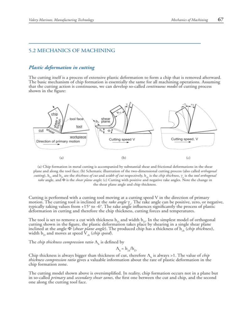
Valery Marinov, Manufacturing Technology Mechanics of Machining 67 5.2 MECHANICS OF MACHINING Plastic deformation in cutting The cutting itself is a process of extensive plastic deformation to form a chip that is removed afterward. The basic mechanism of chip formation is essentially the same for all machining operations. Assuming that the cutting action is continuous, we can develop so-called continuous model of cutting process shown in the figure: h ch shear + frictio n chip cut shea r tool face tool workpiece Direction of primary motion (a) shear bD plane hD Cutting speed V (b) Cutting speed, V (c) (a) Chip formation in metal cutting is accompanied by substantial shear and frictional deformations in the shear plane and along the tool face; (b) Schematic illustration of the two-dimensional cutting process (also called orthogonal cutting), hD and bD are the thickness of cut and width of cut respectively, hch is the chip thickness, γo is the tool orthogonal rake angle, and Φ is the shear plane angle; (c) Cutting with positive and negative rake angles. Note the change in the shear plane angle and chip thickness. Cutting is performed with a cutting tool moving at a cutting speed V in the direction of primary motion. The cutting tool is inclined at the rake angle γo. The rake angle can be positive, zero, or negative, typically taking values from +15o to -6o. The rake angle influences significantly the process of plastic deformation in cutting and therefore the chip thickness, cutting forces and temperatures. The tool is set to remove a cut with thickness hD and width bD. In the simplest model of orthogonal cutting shown in the figure, the plastic deformation takes place by shearing in a single shear plane inclined at the angle Φ (shear plane angle). The produced chip has a thickness of hch (chip thickness), width bD and moves at speed Vch (chip speed). The chip thickness compression ratio Λh is defined by Λh = hch/hD Chip thickness is always bigger than thickness of cut, therefore Λh is always >1. The value of chip thickness compression ratio gives a valuable information about the rate of plastic deformation in the chip formation zone. The cutting model shown above is oversimplified. In reality, chip formation occurs not in a plane but in so-called primary and secondary shear zones, the first one between the cut and chip, and the second one along the cutting tool face. 68 Mechanics of Machining Valery Marinov, Manufacturing Technology Types of cutting Depending on whether the stress and deformation in cutting occur in a plane (two-dimensional case) or in the space (three-dimensional case), we consider two principle types of cutting: Orthogonal cutting the cutting edge is straight and is set in a position that is perpendicular to the direction of primary motion. This allows us to deal with stresses and strains that act in a plane. Oblique Cutting the cutting edge is set at an angle (the tool cutting edge inclination λs). This is the case of three-dimensional stress and strain conditions. cutting edge cutting edge direction of primary motion direction of primary motion (a) s (b) (a) Orthogonal cutting with a cutting tool set normally to the direction of primary motion; (b) Oblique cutting with a cutting tool set at the tool cutting edge inclination angle λs to the direction of primary motion. According to the number of active cutting edges engaged in cutting, we distinguish again two types of cutting: Single-point cutting the cutting tool has only one major cutting edge Examples: turning, shaping, boring Multipoint cutting the cutting tool has more than one major cutting edge Examples: drilling, milling, broaching, reaming Abrasive machining is by definition a process of multipoint cutting. Cutting conditions Each machining operation is characterized by cutting conditions, which comprises a set of three elements: Cutting velocity V: Depth of cut d: Feed f: the traveling velocity of the tool relative to the workpiece. It is measured in m/s or m/min. the axial projection of the length of the active cutting tool edge, measured in mm. In orthogonal cutting it is equal to the actual width of cut bD. the relative movement of the tool in order to process the entire surface of the workpiece. In orthogonal cutting it is equal to the thickness of cut hD and is measured in mm tr-1 in turning, or mm/min in milling and drilling. Valery Marinov, Manufacturing Technology Direction of feed motion Mechanics of Machining Direction of feed motion Direction of primary motion 69 Direction of primary motion Tool cutting edge angle bD=d d bD hD=f f hD To machine a large surface, the tool must be given a feed. (Left) In orthogonal cutting, feed f and depth of cut d coincide with the thickness of cut hD and width of cut bD, respectively. (Right) In oblique cutting, the cutting tool edge is set at an angle (tool cutting edge angle) for easier chip removal. Chip formation There are three types of chips that are commonly produced in cutting, discontinuous chips continuous chips continuous chips with built up edge A discontinuous chip comes off as small chunks or particles. When we get this chip it may indicate, v v v brittle work material small or negative rake angles coarse feeds and low speeds A continuous chip looks like a long ribbon with a smooth shining surface. This chip type may indicate, v v v ductile work materials large positive rake angles fine feeds and high speeds Continuous chips with a built up edge still look like a long ribbon, but the surface is no longer smooth and shining. Under some circumstances (low cutting speeds of ~0.5 m/s, small or negative rake angles), work materials like mild steel, aluminum, cast iron, etc., tend to develop so-called built-up edge, a very hardened layer of work material attached to the tool face, which tends to act as a cutting edge itself replacing the real cutting tool edge. The built-up edge tends to grow until it reaches a critical size (~0.3 mm) and then passes off with the chip, leaving small fragments on the machining surface. Chip will break free and cutting forces are smaller, but the effects is a rough machined surface. The built-up edge disappears at high cutting speeds. Discontinuous chip Continuous chip Tool Secondary shear zone V Built-up edge Tool Continuous chip V Tool V Primary shear zone Scalloped surface Built-up edge fragments Low roughness (a) (b) (c) The type of chip changes with cutting speed. When cutting mild steel, the chip is discontinuous at low cutting velocity (a), forms with a built-up edge at about 0.5 m/s (b), and is continuous with well developed secondary shear zone at high velocity (c). 70 Mechanics of Machining Valery Marinov, Manufacturing Technology Chip control Discontinuous chips are generally desired because they v v v v are less dangerous for the operator do not cause damage to workpiece surface and machine tool can be easily removed from the work zone can be easily handled and disposed after machining. There are three principle methods to produce the favourable discontinuous chip: proper selection of cutting conditions use of chip breakers change in the work material properties Proper selection of cutting conditions Cutting velocity changes chip type as discussed. Since the cutting speed influences to the great extend the productivity of machining and surface finish, working at low speeds may not be desirable. If the cutting speed is to be kept high, changing the feed and depth of cut is a reasonable solution for chip control. At constant cutting speed, the so-called chip map defines the area of desirable chip type as a function of feed and depth of cut: Chip map identifies the area of favourable chip formation for particular work material and cutting tool geometry Chip breaker Chip break and chip curl may be promoted by use of a so-called chip breaker. There are two types of chip breakers external type, an inclined obstruction clamped to the tool face integral type, a groove ground into the tool face or bulges formed onto the tool face Clamp Chip breaker Tool Chip before after Tool chip breaking groove chip breaking bulges Tool Tool Chip breakers and schematic illustration of the action of a chip breaker Change in the work material properties Cut-off carbide insert with an inbuilt advanced chip breaking groove Some elements, for instance lead, when added to steel make chip type and chip removal more favourable. Such steels are referred to as free-machine steels. Increasing the work material hardness (for example by quenching) generally results in production of discontinuous chips.


