Guide To Making ExpressSCH Components
advertisement
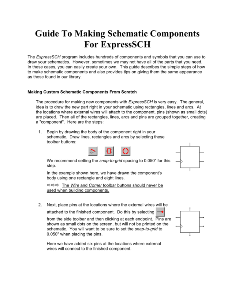
Guide To Making Schematic Components For ExpressSCH The ExpressSCH program includes hundreds of components and symbols that you can use to draw your schematics. However, sometimes we may not have all of the parts that you need. In these cases, you can easily create your own. This guide describes the simple steps of how to make schematic components and also provides tips on giving them the same appearance as those found in our library. Making Custom Schematic Components From Scratch The procedure for making new components with ExpressSCH is very easy. The general, idea is to draw the new part right in your schematic using rectangles, lines and arcs. At the locations where external wires will attach to the component, pins (shown as small dots) are placed. Then all of the rectangles, lines, arcs and pins are grouped together, creating a "component". Here are the steps: 1. Begin by drawing the body of the component right in your schematic. Draw lines, rectangles and arcs by selecting these toolbar buttons: We recommend setting the snap-to-grid spacing to 0.050" for this step. In the example shown here, we have drawn the component's body using one rectangle and eight lines. ððð The Wire and Corner toolbar buttons should never be used when building components. 2. Next, place pins at the locations where the external wires will be attached to the finished component. Do this by selecting from the side toolbar and then clicking at each endpoint. Pins are shown as small dots on the screen, but will not be printed on the schematic. You will want to be sure to set the snap-to-grid to 0.050" when placing the pins. Here we have added six pins at the locations where external wires will connect to the finished component. 3. After placing the pins, double click on each one to assign its pin number and pin name (i.e. CLR). Then drag the pin number and name text to the desired locations. For this step, we recommend selecting a text height of 0.060" and setting the snap-to-grid to 0.025" when positioning the text. 4. Last, group everything together to combine the pieces into a single component as follows: Select your new part by clicking and then drag the mouse to enclose all of the rectangles, lines, arcs and pins. From the Component menu, choose the command Group to make component. In the Component Properties dialog box, enter the Part name (i.e. 7474 or 3.3K) and assign it a Part ID (i.e. U1 or R12). ððð If you are making a part to add to your library, then only set the first letter of the Part ID, leaving the number off until the component is inserted into a schematic. For example, assign integrated circuits the letter U, capacitors the letter C, resistors the letter R, and connectors the letter J. Designing Components For a Standard Appearance We recommend designing your custom components so that they have the same overall appearance as those found in our library. By doing that, a schematic drawn with a mixture of our library components and your special components will maintain a professional appearance. Many integrated circuits having numerous pins are drawn as a simple rectangle with lines for each lead. Because they can be very large, make a effort to keep them compact, but also readable and neat. We recommend setting the snap-to-grid to 0.05" and using these dimensions when drawing rectangular components: The width of this component is shown as 0.9 inches. For components having many more pins and long pin names, a larger width can be used. For example, the component ATS908515 in our library has a width of 1.4 inches. After placing the pins (shown below as small dots) at the ends of the lines on the component, double click on each one to assign its Pin number and Pin name in the Pin Properties dialog box. In the same dialog box, selecting a text height of 0.060" will give the printed pin number and name text the same appearance as we use. Once the Pin number and Pin name values are set, you will need to drag their text to the desired locations. Before positioning the text, we recommend setting the snap-to-grid to 0.025" . With the snap set to 0.025", the Pin numbers are placed such that they sit about 0.006" above the pin and 0.025" from the edge of the component. The Pin name text is positioned so that it is centered vertically with the pin and about 0.035" from the component's edge. The pin numbers and name are also positioned so that the text is justified along the edge of the component. It is our conventions to place the power lines at the top of the component and the ground lines at the bottom. The last step in creating a component is to group all of its parts together using the Group to make component command. This command will display the Component Properties dialog box where the Part name (i.e. AT90S2313) and Part ID (i.e. U12) is set. When creating an IC component that is to be added to your library, the Part ID is usually set to just U, then the number following the U is added later. Once the Part name and Part ID values are set, you will need to drag their text to the desired locations. We recommend setting the snap-to-grid to 0.025" before positioning the text. Here you can see that the U is placed near the upper left corner of the component and the Part name is placed in the middle. The orientation of the Part name text (set in the Component Properties dialog box) is set so that it reads from top to bottom. Naming Components and Saving Them After a component has been created, you will want to save it in your component library. Once saved, it will then appear in the list of Custom components shown in the Component and Symbol Manager dialog box. To save a component, select the Save custom component command from the Component menu. At this point, you will be asked to enter a name for the new component. You can enter any name you like, however the name can not be longer than 61 characters and can not include these symbols: / \ : * ? " < > | When entering the name, we recommend using the same naming standard that we use. By following our convention, your names will be arranged in the Component Manager dialog box in the same order as ours. Below are the guidelines for our naming convention. We begin component names with a Component category. Here are the ones we use: Connector for connectors IC for integrated circuits Misc for batteries, relays, motors… Passive for resistors, capacitors, inductors… Semiconductor Switch - for transistors, diodes, LEDs… for switches and buttons Following the "IC" Component category, we generally add an abbreviated name of the IC manufacture. These are examples of the abbreviations we use: • • • • • • • • • • AMD Allegro Analog devices Atmel Burr Brown Dallas Semi Fairchild Fujitsu Hitachi Semi Intersil - • • • • • • • • • Linear Technology Maxim Microchip National OKI Philips Semi ST Micro TI Toshiba - Next, the component's part number is added. Letters in the part number are written in upper case. Following the part number, a short description of the part can optionally be added. Here are a few examples: LM4861 - Amplifier LM7805 - Regulator AT90S2313 - Microcontroller MAX873 - Voltage reference ððð Note that only the first letter of the description is in upper case and the words are separated by spaces. In some cases a component package type is added to the end of the name. This is done when a component is available in multiple packages, each having different pin numbers. These are examples of a few of the package type abbreviations that we use: DIP-40 PLCC-44 QFP-64 SOIC-20 SSOP-28 ððð It is very important when picking package type, that the name be based on the package name used in the ExpressPCB program. Double check within the ExpressPCB program to verify that the package name you have selected has pad sizes and spacing appropriate for your component. ______________ Here are several examples of component names using the ExpressSCH naming convention with all of the fields discussed above: IC - AMD - AM29DL322 - Flash memory IC - Maxim - MAX232 - Line driver receiver IC - National - LM7805 - Regulator - TO-92 IC - National - LM7805 - Regulator - TO-220 IC - Atmel - AT90S8515 - Microcontroller - PLCC-44 IC - Atmel - AT90S8515 - Microcontroller - DIP-40 Modifying Components From Our Library In some cases, it is fastest to build a new component by starting with a close fit from our library. In other cases it is handy to make simple changes to one of our library components so that its appearance is better suited for your schematic. For example, you may want to rearranging the order the pins. Modifying a component from our library is easily done by first inserting the component into your schematic. Next select the component with the mouse and then ungroup it using the Ungroup component command from the Component menu. Now move things around or make any other changes you wish using the methods described above. Finally, regroup it back together to create the new part using the Group to make component command. The changes that you make will not affect the original part in our ExpressSCH library. Creating Components With Multiple Gates Some integrated circuits have multiple gates in one chip. For example a 74LS32 TTL component includes four OR gates in a 14 pin DIP package. Here is the procedure for creating schematic symbols that have multiple gates in a single package: 1. Create the first gate using the steps listed above in the Making Custom Schematic Components From Scratch section. The first gate should include the power supply and ground pins. 2. Assign the pin numbers to each pin on this first gate. 3. Group the first gate together by selecting its pieces and choosing the Group to make component command. 4. In the Components Properties dialog box, fill in the Part name field with the IC name (i.e. 74LS32) and assign the Part ID field to U. 5. Create each of the remaining gates one at a time, grouping them individually using the same steps 1 through 4. On these gates, do not include the power pins. Each gate should have the Part ID set to U and have the same Part name as the first. 6. After all of the gates have been created, save them in your library as a single component. Do this by selecting all the gates with the mouse and then choosing the Save custom component command from the Component menu. Here is an example showing a 74LS32 with its four OR gates: Note that only the first gate includes the power and ground lines, shown as pins 14 and 7. Each of these four gates have been created individually. That way they can be moved around independently in a schematic. However when the component is saved in the library, all four gates that make up one IC package are saved together. When a component with multiple gates is selected from the library and inserted into your schematic, all of the gates will be added at once. Feel free to position each gate individually in the schematic. Be sure to set the same Part ID value for each gate. Keep in mind that the Part ID represents the package, not the individual gate. For example these four gates might all have their Part IDs set to U7. Custom Component Files When a component is saved using the Save custom component command, it is saved in an individual file on your computer and has a .S extension. The name of the file is the same as the one you entered when naming your component. You can find these files in a subdirectory where the ExpressPCB software is installed. Typically ExpressPCB and ExpressSCH are installed in the directory: C:\Program Files\ExpressPCB If this is where you installed our software, then you will find your custom components in the directory: C:\Program Files\ExpressPCB\SchComponents_Custom Feel free to move the component files that you have created from one computer to any other where ExpressSCH is installed. Of course we also recommend that you backup these files for safe keeping. Copyright © 2003, ExpressPCB, www.expresspcb.com
