AP Physics B Lab: Index of refraction, Snell's Law, & Total Internal
advertisement
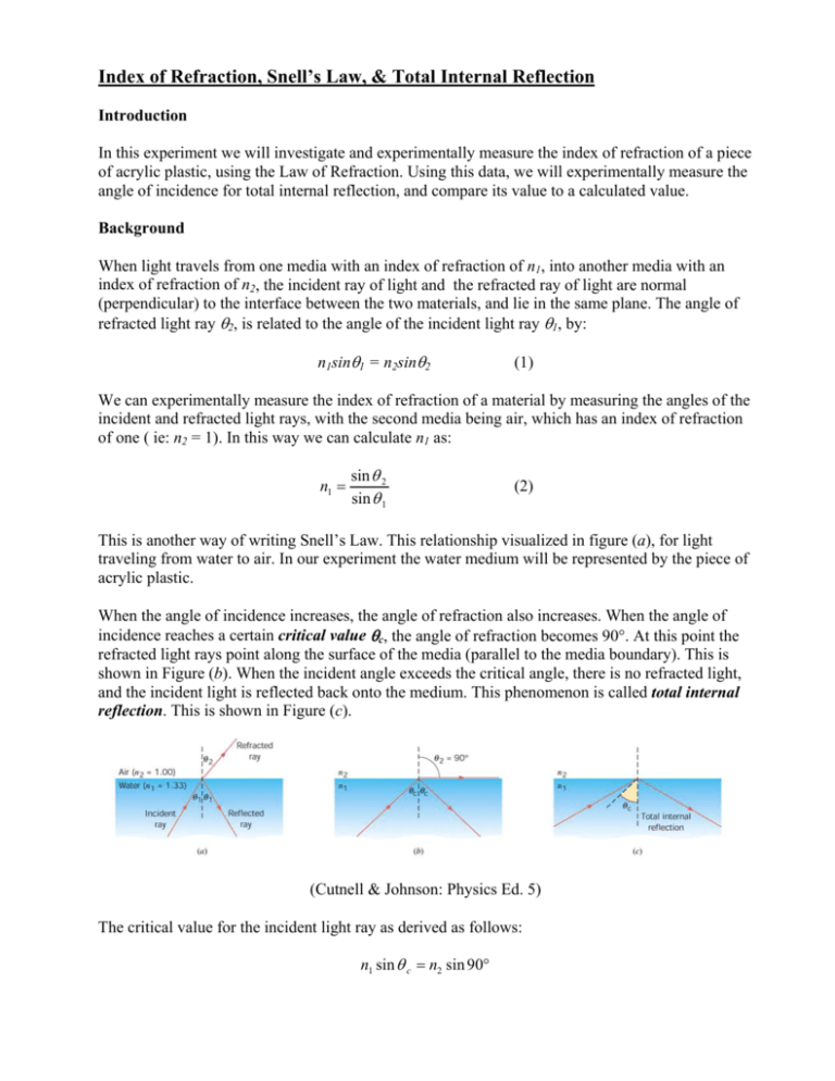
Index of Refraction, Snell’s Law, & Total Internal Reflection Introduction In this experiment we will investigate and experimentally measure the index of refraction of a piece of acrylic plastic, using the Law of Refraction. Using this data, we will experimentally measure the angle of incidence for total internal reflection, and compare its value to a calculated value. Background When light travels from one media with an index of refraction of n1, into another media with an index of refraction of n2, the incident ray of light and the refracted ray of light are normal (perpendicular) to the interface between the two materials, and lie in the same plane. The angle of refracted light ray θ2, is related to the angle of the incident light ray θ1, by: n1sinθ1 = n2sinθ2 (1) We can experimentally measure the index of refraction of a material by measuring the angles of the incident and refracted light rays, with the second media being air, which has an index of refraction of one ( ie: n2 = 1). In this way we can calculate n1 as: n1 = sin θ 2 sin θ 1 (2) This is another way of writing Snell’s Law. This relationship visualized in figure (a), for light traveling from water to air. In our experiment the water medium will be represented by the piece of acrylic plastic. When the angle of incidence increases, the angle of refraction also increases. When the angle of incidence reaches a certain critical value θc, the angle of refraction becomes 90°. At this point the refracted light rays point along the surface of the media (parallel to the media boundary). This is shown in Figure (b). When the incident angle exceeds the critical angle, there is no refracted light, and the incident light is reflected back onto the medium. This phenomenon is called total internal reflection. This is shown in Figure (c). (Cutnell & Johnson: Physics Ed. 5) The critical value for the incident light ray as derived as follows: n1 sin θ c = n2 sin 90° sin θ c = n2 sin 90° n = 2 n1 n1 (3) If the second medium is air, then n2 = 1. Therefore: sin θ c = 1 n1 (4) or ⎛ 1 ⎛1⎞ ⎟⎟ ; in our case, θ c = sin −1 ⎜ ⎜n ⎝ n1 ⎠ ⎝ acylic θ c = sin −1 ⎜⎜ ⎞ ⎟ ⎟ ⎠ (5) The index of refraction for some common substances is shown below. Material (20° C) Index of Refraction Quartz Crystal Glass Obsidian Ice ( 0° C ) 1.544 1.523 1.482 1.309 Equipment Needed The equipment used in this experiment consists of components from the PASCO Model OS-8500, Optics Kit, shown below in Figure 1. Figure 1: PASCO Optics Kit The components required for this experiment are: Optics Bench Ray Plate & Bench Slit Plate Cylindrical Lens (Acrylic) Incandescent Light Source Component Holders (2) Slit Mask Red, Green, Blue Colored Filters The Equipment set-up is shown below in Figure 2. The viewing screen shown is optional, as the light ray can be seen directly from the ray table. Note that the slit plate may be placed behind the slit mask, to provide one light ray as narrow as possible. Figure 2: Experimental Set-Up The Cylindrical Lens is positioned on the Ray Table as shown below in Figure 3. The incident light ray is shown to the left of the lens, and the refracted light ray is shown to the right of the lens. Figure 3 :Cylindrical Lens Position on the Ray Table Procedure 1. Set up the equipment as shown in Figure 2. Adjust the Light Source, and Slit Mask so that a single right ray passes directly through the center of the Ray Table degree scale, and be as narrow as possible. Place the acrylic Cylindrical Lens on the Ray Table as shown in Figure 3, with the incident light ray aligned with 0° on the Ray Table scale. This lens is designed to emulate the conditions shown in figures a-c, above. 2. Without disturbing the alignment of the lens, rotate the Ray Table and set the angle of incidence, θi to 10°. Measure the angle of refraction, θr as shown in Figure 3. Record these values in Table1 below. Calculate the other line items in the table. The calculated index of refraction for the sin θ r Cylindrical Lens, will be the value of (reference equation 2). Complete the table for values sin θ i for the angles of incidence as shown below. Find the average value for the index of refraction for the acrylic Cylindrical Lens, and record it. Angle of Incidence Angle of Refraction 0° sinθi sinθr sinθr sinθi ------- ------ ----- 10° 20° 30° 40° Average nacrylic = _____ Table 1: Data Table for the Acrylic Cylindrical Lens 3. Continue to rotate the Ray Table until the refracted ray is 90° to the incident ray (ie: parallel to the aft surface of the Cylindrical Lens). Refer to Figure b above. Record this critical incident angle below. Now using equation 5, calculate the critical angle, θc, and record below. Continue to slowly rotate the Ray Table and observe what happens to the refracted ray. What do you conclude from this observation? Measured θc = ________° Calculated θc = _________° Observations: The measured and calculated values for the critical angle should agree to within ± .5°. 4. Repeat this experiment with red, green, and blue colored filters and compare the results obtained with white light. The colored filters attach magnetically to the face of the Light Source. Questions | calculated − measured | × 100% . calculated Explain the sources of error and suggest methods for minimizing the error. 1. Calculate the % Error in measuring the critical angle as 2. Does the index of refraction seem reasonable when compared to the table of common substances, shown above. Explain your reasoning. 3. Does the index of refraction for the acrylic Cylindrical Lens vary with the frequency (color) of the incident light? Explain your answer in terms of Snell’s Law. 4. Does the intensity of the incident light rays affect the angle of refraction? Explain why you believe this is true.

