ME 354 Tutorial, Week#12
advertisement
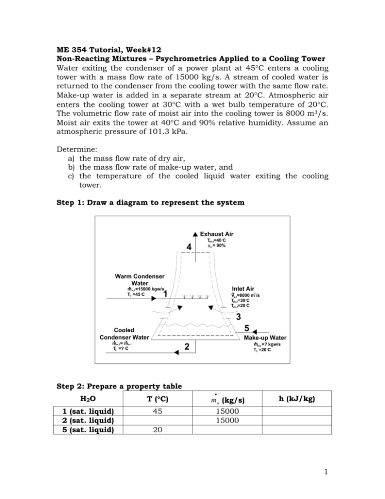
ME 354 Tutorial, Week#12 Non-Reacting Mixtures – Psychrometrics Applied to a Cooling Tower Water exiting the condenser of a power plant at 45C enters a cooling tower with a mass flow rate of 15000 kg/s. A stream of cooled water is returned to the condenser from the cooling tower with the same flow rate. Make-up water is added in a separate stream at 20C. Atmospheric air enters the cooling tower at 30C with a wet bulb temperature of 20C. The volumetric flow rate of moist air into the cooling tower is 8000 m3/s. Moist air exits the tower at 40C and 90% relative humidity. Assume an atmospheric pressure of 101.3 kPa. Determine: a) the mass flow rate of dry air, b) the mass flow rate of make-up water, and c) the temperature of the cooled liquid water exiting the cooling tower. Step 1: Draw a diagram to represent the system Exhaust Air 4 Tdb,4=40 C 4 = 90% Warm Condenser Water Inlet Air mw,1=15000 kgw/s T1 =45 C 1 3 Va,3=8000 m /s Tdb,3=30 C Twb,3=20 C 3 5 Cooled Condenser Water Make-up Water mw,2 = mw,1 T2 =? C mmw =? kgw/s T5 =20 C 2 Step 2: Prepare a property table H2O T (C) m w (kg/s) 1 (sat. liquid) 2 (sat. liquid) 5 (sat. liquid) 45 15000 15000 h (kJ/kg) 20 1 Air 3 4 Tdb (C) 30 40 Twb (C) 20 (%) w (kgv/kga) v (m3/kga) h (kJ/kga) 90 Step 3: State your assumptions Assumptions: 1) The cooling tower operates under steady conditions 2) KE, PE 0 3) Cooling tower is rigid and adiabatic W CV , Q CV 0 4) Assume all liquid water is saturated 5) The pressure is constant throughout the cooling tower at 101.3 kPa. Step 4: Solve Part a) The mass flow rate of dry air can be determined using the volumetric flow rate of moist air drawn into the cooling tower (given in the problem as 8000 m3/s) and the specific volume of this air (on a per kg dry air basis) as shown in Eq1. m a ,3 V v3 (Eq1) The specific volume of the air entering the cooling tower can be determined using the state point of location 3 on the psychrometric chart found with Tdb,3 = 30C and Twb,3 = 20C. From the psychrometric chart, v3 = 0.873 m3/kga Substituting this value and the given volumetric flow rate into Eq1 the mass flow rate of dry air is determined as shown below. m a ,3 V a ,3 v a ,3 m3 8000 s 9163.8 kg a s m3 0.873 kg a Answer a) Part b) To determine the mass flow rate of the make-up water, denoted as m mw , a mass balance can be performed on the water entering/exiting the cooling 2 tower control volume. At location 1 there is a stream of water entering the cooling tower from the condenser, which will be denoted as m w,1 . At location 2 there is a stream of water exiting the cooling tower (to be returned to the condenser), which will be denoted as m w, 2 . From the problem statement, the mass flow rate of the cooled water leaving the cooling tower (to the condenser) is equal to the mass flow rate of water entering the cooling tower (from the condenser). This is expressed in Eq2. (Eq2) m w,1 m w, 2 m w At location 3, there is moisture entering the cooling tower control volume carried in by the incoming air, which will be denoted as m v,3 . At location 4, there is moisture leaving the cooling tower control volume carried out by the exiting air, which will be denoted as m v , 4 . The mass balance on the cooling tower water is performed in Eq3. m w m w m v,3 m v, 4 m mw 0 m mw m v, 4 m v,3 (Eq3) Note: Eq3 could have been developed immediately by reasoning that the amount of water that needs to be “made-up” for will be equal to the amount of moisture that is picked up in the cooling tower by the air and exhausted. The mass flow rate of water vapor at 3 and 4 can be expressed in terms of the corresponding mass flow rates of dry air at location 3 and 4 and their respective humidity ratios w3 and w4 as shown in Eq4 and Eq5. (Eq4) m v ,3 w3 m a ,3 (Eq5) m v , 4 w4 m a , 4 Substituting Eq4 and Eq5 into Eq3, Eq6 is obtained. m mw m v , 4 m v ,3 w4 m a , 4 w3 m a ,3 (Eq6) Since steady operation of the cooling tower has been assumed. The mass flow rate of air through the tower should remain constant. This is expressed in Eq7. m a ,3 m a , 4 m a (Eq7) 3 Substituting Eq7 in Eq6, Eq8 is obtained. (Eq8) m mw m a ( w4 w3 ) Recall that the mass flow rate of dry air was determined in part a). The humidity ratio of the air entering the cooling tower can be determined from state point 3 on the psychrometric chart. From the psychrometric chart, w3 = 10.6 gv/kga = 0.0106 kgv/kga Unfortunately, state point 4 (Tdb,4 = 40C and =90%) is off the psychrometric chart so w4 will have to be calculated using equation 1311b from Cengel and Boles as shown below. From Table A-4 @ T= 40C, Pg = 7.384 kPa. w4 0.622 4 Pg P 4 Pg kg 0.622(0.9)(7.384) 0.0437 v 101.3 0.9(7.384) kga Substituting these values into Eq8, the mass flow rate of the make-up water can be determined. kg kg m mw m a ( w4 w3 ) 9163.8 a 0.0437 0.0106 v s kg a m mw Answer b) kg 303.3 v s Part c) The temperature of the cooled liquid water exiting the cooling tower can be determined if its enthalpy is known. Since the liquid exiting the cooling tower is assumed to be a saturated liquid, its enthalpy can be used to interpolate in Table A-4 to determine its temperature. To find the enthalpy of the water exiting the cooling tower an energy balance on the cooling tower control volume can be performed. At location 1, the rate of energy entering the control volume carried by the stream of water coming from the condenser is m w hw,1 . At location 2, the stream of water leaving the cooling tower is carrying away energy at a rate of m w hw, 2 . At location 4 3, the moist air carries energy into the control volume at a rate of m a h3 into the control volume. At location 4, the moist air leaving the cooling tower control volume carries energy away at a rate of m a h4 . The make-up water carries energy into the control volume at a rate of m mw hmw . Combining all of these statements into one expression to obtain Eq9. (Eq9) m w hw,1 m w hw, 2 m a h3 m a h4 m mw hmw 0 By rearranging Eq9, the enthalpy of the water at location 2 can be determined, as shown in Eq10. hw, 2 hw,1 m a (h3 h4 ) m mw hmw (Eq10) mw m a and m mw have previously been determined and m w is given in the problem statement leaving hw,1, h3, h4, and hmw to be determined before hw,2 can be solved for. hw,1 Since saturated liquid water was assumed at location 1, hw,1 can be determined from Table A-4 using T1 = 45C. kJ hw,1 188.45 kgw h3 Using state point 3 on the psychrometric chart h3 can be determined. kJ h3 58 kga h4 As stated previously, state point 4 is off the psychrometric chart so h4 must be calculated. Using equation 13-1a from Cengel and Boles, the enthalpy of DRY AIR alone can be determined as shown below. kJ kJ ha , 4 c p T 1.005 (40 C ) 40.2 kga kga C Note: the above calculation is in fact a calculation of an enthalpy difference with the enthalpy at 0C being subtracted from the enthalpy of interest. The enthalpy at 0C in this case is zero (because 0C is the zero 5 reference point for enthalpy). The enthalpy difference calculation in full would appear as shown below. ha , 4 ha @ 0C c p (T4 [ K ] 273K ) ha , 4 0 c p T4 [ C ] 273[ K ] 273K ha , 4 c p T4 [ C ] kJ kJ ha , 4 1.005 (40 C ) 40.2 kg a kg a C The enthalpy of the MOISTURE in the air can be determined from Table A-4 for hg@ T = 40C. kJ hv, 4 hg (T ) 2574.3 kgv To combine the dry air and moisture enthalpies at location 4 into one term, h4, the enthalpy of the moisture must be converted to a “per kg of dry air” basis, which is accomplished by multiplying it by the humidity ratio, w4. kJ kgv kJ kJ h4 ha , 4 w4 hv , 4 40.2 0.0437 2574.3 152.7 kga kga kgv kga hmw Since saturated liquid water was assumed at location 5 hmw can be determined from Table A-4 using T5 = 20C. kJ hmw 83.96 kgw Substituting these values into Eq10, the enthalpy of the water at location 2 can be determined as shown below. hw , 2 kJ kJ kg kg w 9163.8 a (58 152.7) (83.96) (303.3) s kg s kg kJ a w 188.45 kg kg w 15000 w s kJ kJ kJ hw, 2 188.45 56.16 132.3 kgw kgw kgw 6 As stated previously, since saturated liquid water was assumed at location 2, hw,2 can be used to find the corresponding temperature in Table A-4. From Table A-4 it is found that hw,2 lies in between the enthalpies corresponding to temperatures of 30C and 35C. Interpolating between these two values, the temperature of the water exiting the cooling tower can be determined as shown below. T2 30 C 132.3 125.79 146.68 125.79 35 C 30 C T2 31.6[ C ] Answer c) Step 5: Summary a) the mass flow rate of dry air is 9163.8 kga/s b) the mass flow rate of make-up water is 303.3 kgw/s, and c) the temperature of the cooled liquid water exiting the cooling tower is 31.6C. 7
