A device (typically analogue) used to extend a LAN. It connects
advertisement
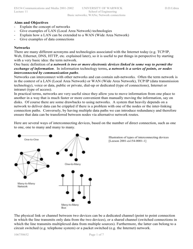
ES154 Communications and Media 2001-2002 UNIVERSITY OF WARWICK Lecture 11 School of Engineering Basic networks; WANs; Network connections D.D.Udrea Aims and Objectives - Explain the concept of networks - Give examples of LAN (Local Area Network) technologies - Explain how a LAN can be extended to a WAN (Wide Area Network) - Give examples of data connections Networks There are many different acronyms and technologies associated with the Internet today (e.g. TCP/IP, Web, Ethernet, DNS, HTTP, etc. explained later), so it is useful to put things in perspective by starting with a very basic idea: the term network. One basic definition of a network is two or more electronic devices linked in some way to permit the exchange of information. In information technology terms, a network is a series of points, or nodes interconnected by communication paths. Networks can interconnect with other networks and can contain sub-networks. Often the term network is in the context of a LAN (Local Area Network) or WAN (Wide Area Network), TCP/IP (data transmission technology), voice or data, public or private, dial-up or dedicated (type of connections), Internet or intranet (type of access). In practical terms, networks are very useful since they allow you to move information from one place to another in a way that is much faster or more convenient than manually moving the information, say on disks. Of course there are some drawbacks to using networks. A system that heavily depends on a network to deliver data can be crippled if there is a problem with one of the nodes or the inter-linking connection paths. Conversely, by having multiple data paths we can introduce redundancy and therefore ensure that data can be transferred between nodes via alternative network routes. Here are several ways of interconnecting devices, based on the number of direct connection, such as one to one, one to many and many to many. Illustration of types of interconnecting devices [Leeson 2001-es154-0001-1] The physical link or channel between two devices can be a dedicated channel (point to point connection in which the line transmits only data from the two devices), or a shared channel (switched connections in which the line transmits multiplexed data from multiple sources). Furthermore, the latter can belong to a circuit switched (e.g. telephone system) or a packet switched (e.g. the Internet) network. 106750652 Page 1 of 7 ES154 Communications and Media 2001-2002 UNIVERSITY OF WARWICK Lecture 11 School of Engineering Basic networks; WANs; Network connections D.D.Udrea In general a network technology is classified into one of three broad categories, depending on the size of network that can be created: A Local Area network (LAN) can span a single building or campus or can be extended between a few small size sites. A Wide Area Network (WAN) can span multiple cities, countries or continents and connect an arbitrarily large number of computers. LAN topologies Topology Star Ring Bus Description Each computer attaches to a central point called a hub. The computers send or receive data through the hub, which is responsible for connecting the sender with the recipient. Any computer can send data at any one time. Computers are connected in a closed loop and each computer connects directly to two others. Only one computer has access to the shared ring and can send data at any one time. Data from one computer has to pass through all the others and come back to the original sender before the transmission is complete. All computers attach to a single, shared cable. Any computer can send data and all computers receive it. However, computers must coordinate to ensure that only one computer sends data at any one time. Examples ATM network, ARCnet IBM Token ring, FDDI Ethernet, LocalTalk, Wireless LANs Advantages and Disadvantages (A) Network independent of individual connections; (A) Computers can send data simultaneously; (A) Works over long distances at high speeds; (D) Long wires; (A) Easy to coordinate and check that network operates correctly; (D) Entire network down if one cable is cut. (D) Computers can only send data (A) Fewer wires (A) Very fast (D) Prone to collision; (D) Works over short distances; Illustration of the star topology [Comer 2001 Chapter8]. Illustration of a ring topology [Comer 2001 Chapter 8]. Illustration of a bus topology [Comer 2001 Chapter8]. WAN examples Many technologies have been created for experimental and production use in WANs. Examples of such technologies are ARPANET (data), X.25 (voice), Frame Relay (data), SMDS (data), ATM (voice and data). 106750652 Page 2 of 7 ES154 Communications and Media 2001-2002 UNIVERSITY OF WARWICK Lecture 11 School of Engineering Basic networks; WANs; Network connections D.D.Udrea A small WAN formed by interconnecting packet switches. Connections between packet switches usually operate at a higher speed than connections to individual computers [Comer 2001 Chapter 13]. A bridge using a leased satellite channel to connect LAN segments at two sites. A satellite bridge can span arbitrary distance [Comer 2001 Chapter 11]. Network Hardware At the lowest level, all computer communication involves encoding data in a form of energy, and sending the energy across a transmission medium. For example, electric current can be used to transfer data across a wire, or radio waves can be used to carry data through the air. To connect to a network, a computer needs dedicated hardware. The hardware available dictates the bandwidth (hence speed) of the data transfer. Because hardware devices attached to a computer perform the encoding and decoding of data, programmers and users don’t need to know the details of data transmission. However, because a major role of the communication software is to handle errors and failures that appear due to the hardware, understanding such software requires a basic knowledge of data transmission and hardware. Standards To ensure that communication hardware built by different vendors will interoperate, the specifications for communication systems are standardised. A standard is a document which contains a list of specifications about a specific communication technology, from timing of signals to electrical voltages and currents, from number of bits to characters and codes. Examples of such standards are RS-232-C (defines serial, asynchronous communication over short distance), RS-422 (extension of RS232), ASCII (binary representation of characters). Network media Cables Unshielded twisted pair (UTP) Shielded twisted pair (STP) Coaxial cable 106750652 Description 4 pairs of copper wires inside the same plastic jacket; twists minimise interference with other cables. RJ-45 connector 2 pairs of copper wires, individually shielded in foil, surrounded by a braided metal shielding. IBM data connector Single copper wire surrounded by a braided metal shielding. BNC connector Advantages Low cost; Easy to repair; Disadvantages Signal suffers from interference; Application Short length LAN and Telephone; BW 1-200 MHz Low cost; Easy to repair; Less interference but bulky; Short length high speed LAN; 0.1-1 GHz Short length LANs; Ethernet and ARCnet 0.3-10 GHz Low cost; Easy to repair; Page 3 of 7 ES154 Communications and Media 2001-2002 UNIVERSITY OF WARWICK Lecture 11 School of Engineering Basic networks; WANs; Network connections Fibre optic cable A bunch of optic fibres in a plastic sleeve. Each fibre is made of glass and cladding and surrounded by reinforcing layers of plastic. ST fibre connector Wireless Infrared Description Infrared light through air. Radio Radio waves through air or vacuum Microwaves through air Microwave No interference; Low attenuation; One fibre only; Huge bandwidth Expensive; Difficult to pinpoint and repair D.D.Udrea Long distance and high traffic LANs and WANs; THz Advantages Mobile, Inexpensive, Huge bandwidth Flexible, mobile Disadvantages Short distance Line of sight Application Wireless LAN; Short distance portable computers BW THz Large antennas Interference, Wireless LAN and WAN Ground stations, satellites, cellular MHZ Flexible, mobile, directional Line of sight Wireless LAN and WAN point to point, ground stations, satellite, cellular 2-30 GHz Network interfaces Interface Network Card or LAN adapter or NIC (Network Interface Card) Modem MOdulator/DEModulator) DSU/CSU (Data Service Unit/Channel service unit) Description A hardware device that plugs into a computer internal bus and connects the computer to a network. It is built for a specific network technology. A device that encodes/decodes digital information in a carrier wave for transmission across (from) copper wire or a dialup telephone connection (typically analogue). A device that connects a leased digital data circuit to computer equipment. It translates between the digital format used by the telephone companies and the format used by the computer industry. Illustration of dialup modems that use the voice telephone system to communicate. To the telephone system, a dialup modem appears to be a telephone [Comer 2001 Chapter 6]. Illustration of a digital circuit with a DSU/CSU on each end. The DSU/CSU converts between the digital standards used in the telephone system and those used by computer vendors [Comer 2001 Chapter 12]. Organization of the hardware in a computer attached to a LAN. Because it is powerful and independent, the network interface hardware does not use the CPU when transmitting or receiving data [Comer 2001 Chapter 9]. 106750652 Page 4 of 7 ES154 Communications and Media 2001-2002 UNIVERSITY OF WARWICK Lecture 11 School of Engineering Basic networks; WANs; Network connections D.D.Udrea Network hardware components Hardware Transceiver Hub Repeater Bridge Router Route Server Switch Description A device that connects a NIC in a computer to a physical medium. Are used with Ethernet. An electronic device that implements a network. Computers connected to a hub can communicate as if they attach to a network. A device (typically analogue) used to extend a LAN. It connects directly two cable segments, continuously monitors the signals on each segment and re-transmits an amplified version of the signals tot he other segment. A more advanced type of repeater which re-transmits signals only as far as necessary and can isolate problems which appear on the cable. The basic block of an Internet. A computer that attaches to two or more networks and forwards packets in more than one direction according to information in its routing table. It runs IP. A router can interconnect networks that use different technologies (ie media, addressing scheme, frame format) A server that contains complete routing information for the global Internet. All route servers together form the routing arbiter system. The basic block of a switched network (e.g. star network). It uses the destination address of a data block to determine which computer should receive the data. A bridge connecting LAN segments in two buildings. For example, an optical fibre is used to connect the bridge to a remote LAN segment [Comer 2001 Chapter 11]. A repeater R connecting two Ethernets. The repeater connects directly to the cable; it does not use a transceiver. [Comer 2001 Chapter 11]. The concept underlying a switched LAN. Electronic circuits in the switch provide each computer with the illusion of a separate LAN segment connected to other segments by bridge [Comer 2001 Chapter 11]. Network software Communication protocols Basic communication hardware consists of mechanisms that can transfer bits from one point to another. However, using raw hardware to communicate is cumbersome and inconvenient. To aid programmers, computers on a network use complex software that provides convenient, high-level interface for applications. Thus, most applications rely on network software to communicate and they do not handle hardware directly. All parties involved in a communication must agree on a set of rules to be used when exchanging messages, which specifies the format of messages and the appropriate actions required to handle each message. This is called a communication protocol. 106750652 Page 5 of 7 ES154 Communications and Media 2001-2002 UNIVERSITY OF WARWICK Lecture 11 School of Engineering Basic networks; WANs; Network connections D.D.Udrea Instead of having a single, giant protocol that specifies complete details for all possible forms of communication, designers have chosen to divide the problem into subpieces and design a separate protocol for each subpiece. OSI model (for reference only, not for the exam) A good way of understanding the various protocols and technologies associated with networks is to look at the ISO (International Standards Organisation) seven-layer model of networks, also known as the OSI (Open Systems Interconnect) model[Travis, Chapter 1]. This model sets the standards for networks by defining how each aspect should work – from the physical interconnections on the network through to how data is communicated. The seven-layer ISO OSI model is essential as it dictates how each computer on the Internet (i.e. corporate LAN, home computer etc.) must behave in order to facilitate data transfer. Without it, Internet computers could (and most probably would) have incompatible network architectures. The topmost layers are the most abstract, each one built upon the more primitive lower layers. The layers can be independent of each other so, for example, programmers can concentrate on writing network software (higher level) without having to worry about the physical connectivity (lower level). A brief description of each layer is as follows: 1. Physical: Information is encoded ultimately into electrons or electromagnetic waves. The physical layer defines the voltages and signal levels for a type of network. Part of the Ethernet standard, for example, defines the Physical layer. Standards such as RS232, 10-Base-T, Twisted Pair, Fibre-Optic, modems and others, are also involved in this layer. 2. Data Link: This layer is concerned with reliable and error-free data transfer across nodes, with facilities such as bit error detection. 3. Network: The network layer is a type of kernel service that uses unique source and destination addresses to send data over the network. IP (Internet Protocol) is part of this layer, since is specifies how to identify source and destination addresses with “IP numbers”, e.g. 128.34.22.110 4. Transport: The transport layer segments messages into smaller units called packets for transmission. It controls the transmission of packets, making sure that they arrive in sequence and that no packets are missing. TCP (Transmission Control Protocol) is part of this layer. 5. Session: This layer connects and manages the sessions between two end users. Services like DNS (Domain Name Service), login, authentication using passwords, etc. are part of this layer. 6. Presentation: The Presentation layer helps with initiating and terminating connections, and isolates the Application layer from differences between various types of computers in the way they represent data internally. 7. Application: This is the top-end user layer. It provides approximate meaning and functionality to the transferred data. For example, FTP and HTTP protocols (both described later) fall into this category. The historic ISO 7-Layer Reference Model. A layering model is a tool to help protocol designers construct a suite of protocols that solves all communication problems [Comer 2001 Chapter 16] 106750652 Page 6 of 7 ES154 Communications and Media 2001-2002 UNIVERSITY OF WARWICK Lecture 11 School of Engineering Basic networks; WANs; Network connections D.D.Udrea Physical layer One of the major limitations to building Internet-enabled systems is the available bandwidth, or how many bits per second can be transmitted. An example of limited bandwidth can be seen when you watch real-time video with an analogue modem. Often special compression techniques have to be used in order to enable the video to appear smooth and if the connection is not consistent, then the video stops. This restriction in available bandwidth is generally due to limitations of the Physical layer. Internet Hardware Interface – physical layer Cellular modem (wireless) e.g. mobile phone Serial modem (using analogue phone line) ISDN modem T1 ADSL modem Cable modem T3 10-BaseT Ethernet* 100-Base-T Ethernet* Gigabit Ethernet* Theoretical Maximum Speed 19 Kbit/s 56 Kbit/s 128 Kbit/s 1.544 Mbit/s 9 Mbit/s 30 Mbit/s 44.736 Mbit/s 10 Mbit/s 100 Mbit/s 1000 Mbit/s *LAN (Local Area Network) technologies References: Comer, Douglas - Computer networks and Internets with Internet applications / Douglas E. Co. - 3rd ed. - Upper Saddle River, N.J.; London: Prentice Hall, 2001. – ISBN 0-13-091449-5 QA 74.2.C6 Leeson Mark – ES154 Communications and Media – lecture notes : es154-0001-1.pdf, 2001 106750652 Page 7 of 7
