Chapter 11 Application of hard magnets
advertisement
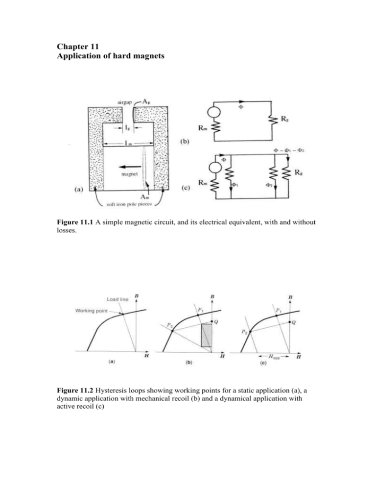
Chapter 11 Application of hard magnets Figure 11.1 A simple magnetic circuit, and its electrical equivalent, with and without losses. Figure 11.2 Hysteresis loops showing working points for a static application (a), a dynamic application with mechanical recoil (b) and a dynamical application with active recoil (c) Figure 11.3 Influence of permanent magnet properties of a dc motor and a loudspeaker Figure 11.4 Comparison of the magnetic field produced by a) a point dipole m and b) a line dipole λ Figure 11.5 Designs for magnetic cylinders which produce a uniform transverse field. Figure 11.6 Some cylindrical magnet structures which produce inhomogeneous fields: (a) a quadrupole field (b) a hexapole field and (c) a uniform field gradient. Figure 11.7 A wiggler magnet used to generate intense electromagnetic radiation from an electron beam. Figure 11.8 (a) Open-gradient magnetic and (b) electromagnetic separation with permanent magnets. Figure 11.9 Field and force patterns around a cylindrical iron wire in a high-gradient magnetic separator. Figure 11.10 Permanent magnet variable flux sources: (a) a double Halbach cylinder. (b) four–rod mangle. Figure 11.11 A MULTIMAG permanent-magnet variable flux source and controller. The magnet head produces a variable field of up to 1.8 T in any transverse direction in the bore. Figure 11.12 A vector vibrating-sample magnetometer based on a MULTIMAG Figure 11.13 A magnetic toroid, cut and separated to produce a field in the air gap. Figure 11.14 Two designs for switchable magnetic clamps. (a) is a rotatable magnet design shown in the ‘on’ position, (b) is a design where the magnet array is displaced laterally, shown in the ‘off’ position. Figure 11.15 (a) A face-type coupling with four axially-magnetized segments, (b) A 2:1 magnetic gear with radially-magnetised segments. Figure 11.16 Two elementary magnetic bearings made from axially-magnetised rings; (a) a radial bearing and (b) an axial bearing. Figure 11.17 A linear magnetic bearing. Figure 11.18 A Maglev system based on eddy-current repulsion. Figure 11.19 A magnetically-compensated hinge. Figure 11.20 Variable-reluctance sensor. Figure 11.21 A flat voice-coil actuator for a personal-computer disk drive. Figure 11.21 Moving-iron actuators: (a) print hammer and (b) reed switch. Figure 11.22 DC motor designs: (a) brush motor with magnets on the stator and (b) brushless motor with magnets on the rotor. Figure 11.23 Motors: (a) A two-pole dc brush motor, (b) a two-pole four-phase brushless dc motor and (c) a variable reluctance motor. Figure 11.24 Variants pf the brushless dc motor: (a) normal design (b) cup-type (c) disk-type. 1 – magnet; 2 – stator; 3 – stator winding; 4 – position sensor. Figure 11.24 A four pole synchronous motor with a permanent magnet rotor. A 16 bar squirrel cage winding is incorporated so that the machine will operate as an induction motor for startup. Figure 11.25 A two pole stepping motor used in clocks and watches. In watches the magnet made of bonded Sm2Co17 has a mass of a few mg. Figure 11.26 Miniature hybrid stepping motor.


