Section #26 09 23.01 - Metering and Switchboard Instruments
advertisement
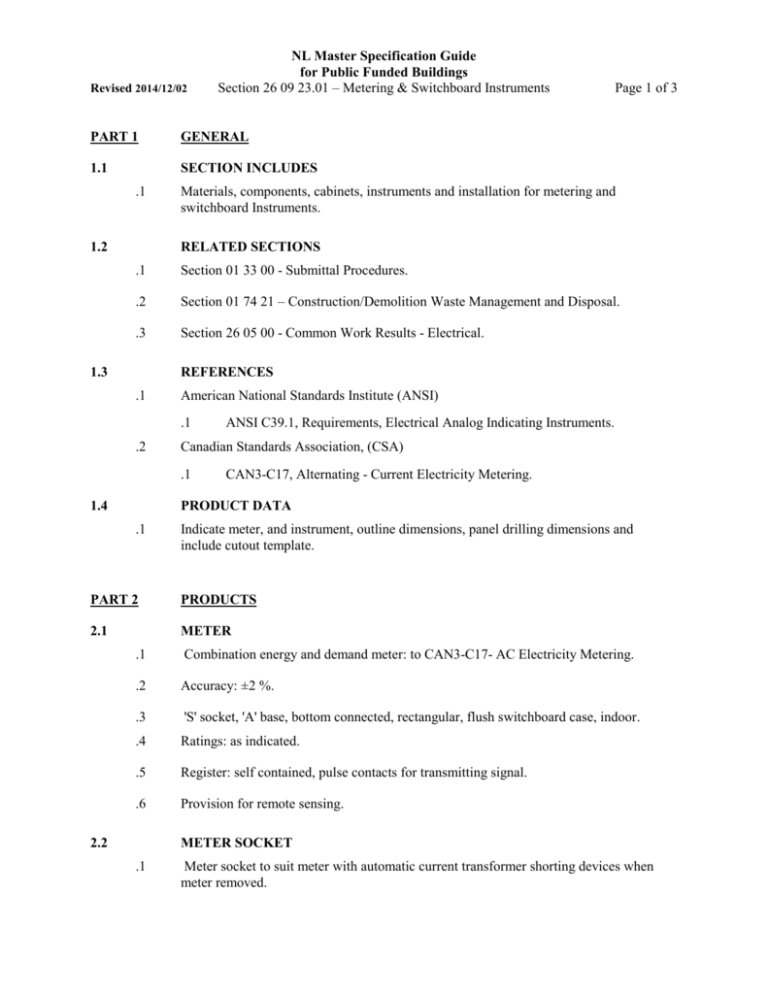
Revised 2014/12/02 NL Master Specification Guide for Public Funded Buildings Section 26 09 23.01 – Metering & Switchboard Instruments PART 1 GENERAL 1.1 SECTION INCLUDES .1 1.2 Page 1 of 3 Materials, components, cabinets, instruments and installation for metering and switchboard Instruments. RELATED SECTIONS .1 Section 01 33 00 - Submittal Procedures. .2 Section 01 74 21 – Construction/Demolition Waste Management and Disposal. .3 Section 26 05 00 - Common Work Results - Electrical. 1.3 REFERENCES .1 American National Standards Institute (ANSI) .1 .2 Canadian Standards Association, (CSA) .1 1.4 ANSI C39.1, Requirements, Electrical Analog Indicating Instruments. CAN3-C17, Alternating - Current Electricity Metering. PRODUCT DATA .1 Indicate meter, and instrument, outline dimensions, panel drilling dimensions and include cutout template. PART 2 PRODUCTS 2.1 METER .1 Combination energy and demand meter: to CAN3-C17- AC Electricity Metering. .2 Accuracy: ±2 %. .3 'S' socket, 'A' base, bottom connected, rectangular, flush switchboard case, indoor. .4 Ratings: as indicated. .5 Register: self contained, pulse contacts for transmitting signal. .6 Provision for remote sensing. 2.2 METER SOCKET .1 Meter socket to suit meter with automatic current transformer shorting devices when meter removed. NL Master Specification Guide for Public Funded Buildings Revised 2014/12/02 Section 26 09 23.01 – Metering & Switchboard Instruments 2.3 METER CABINET .1 2.4 Page 2 of 3 Sheet steel CSA enclosure with meter backplate, to accommodate meters, test terminal block and associated equipment, factory installed and wired. METERING INSTRUMENT TRANSFORMER CABINET .1 2.5 Sheet steel CSA enclosure to accommodate potential and current transformers. TEST TERMINAL BLOCKS .1 2.6 Test terminal blocks: as required. INDICATING INSTRUMENTS .1 Analogue or digital indicating instruments: to ANSI C39.1, Electrical Analogue Indicating Instruments, 1% accuracy, switchboard mounting, flush, case size 87 by 112 mm rectangular 1800 scale, operated from shunt current transformer. .1 .2 .3 .4 .5 .6 2.7 Ammeter: true RMS range as indicated to suit project requirement. Voltmeter: true RMS range 0-250 V a.c. and 0-600 V a.c., as indicated. Wattmeter: range as indicated. Varmeter: range as indicated. Frequency meter: range 0-60 Hertz. Power factor meter: range 0-1.0. INSTRUMENT SELECTOR SWITCHES .1 Voltmeter and Ammeter selector switches: rotary, multi-position, maintained contacts, panel mounting, round notched handle, rated to suit instruments, nameplate marked as indicated to coincide with each rotary position. Ammeter selector switches designed to preclude opening of current circuits. .2 Four position ammeter selector switches identified "off-A-B-C". .3 Four position voltmeter selector switches identified "A-B, B-C, C-A, off". .4 Seven position voltmeter selector switches identified "A-B, B-C, C-A, off, A-N, B-N, CN". 2.8 SHOP INSTALLATION .1 Install meters and instrument transformers in separate compartment of switchboard. .2 Install instruments on switchboard. .3 Ensure adequate spacing between current transformers installed on each phase. .4 Verify correctness of connections, polarities of meters, instruments, potential and current transformers, transducers, signal sources, electrical supplies. NL Master Specification Guide for Public Funded Buildings Revised 2014/12/02 Section 26 09 23.01 – Metering & Switchboard Instruments PART 3 EXECUTION 3.1 Page 3 of 3 METERING INSTALLATION .1 Install meters and instruments in location free from vibration and shock. .2 Make connections in accordance with diagrams. .3 If applicable, ensure power factor corrective equipment connected on load side of meter. .4 Connect meter and instrument transformer cabinets to ground. .5 Locate meters within 9 m of instrument transformers. Use 32 mm conduit for interconnections. Use separate conduit for each set of current transformer connections, exclusive for metering. 3.2 FIELD QUALITY CONTROL .1 Conduct tests in accordance with Section 26 05 00- Common Work Results – Electrical and Section 01 91 13 – Commissioning (Cx) Requirements and in accordance with manufacturer's recommendations. .2 Perform simulated operation tests with metering, instruments disconnected from permanent signal and other electrical sources. .3 Verify correctness of connections, polarities of meters, instruments, potential and current transformers, transducers, signal sources and electrical supplies. .4 Perform tests to obtain correct calibration. .5 Do not dismantle meters and instruments. END OF SECTION


