Design of Small Base Plates for Wide Flange Columns
advertisement
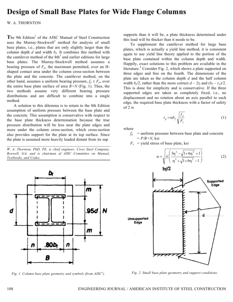
Design of Small Base Plates for Wide Flange Columns W. A. THORNTON The 9th Edition1 of the AISC Manual of Steel Construction uses the Murray-Stockwell2 method for analysis of small base plates, i.e., plates that are only slightly larger than the column depth d and width bf. It combines this method with the cantilever method of the 8th3 and earlier editions for large base plates. The Murray-Stockwell method assumes a bearing pressure of Fp, the maximum permitted, over an Hshaped contact area under the column cross-section between the plate and the concrete. The cantilever method, on the other hand, assumes a uniform bearing pressure, fp ≤ Fp, over the entire base plate surface of area B×N (Fig. 1). Thus, the two methods assume very different bearing pressure distributions and are difficult to combine into a single method. A solution to this dilemma is to return to the 8th Edition assumption of uniform pressure between the base plate and the concrete. This assumption is conservative with respect to the base plate thickness determination because the true pressure distribution will be less near the plate edges and more under the column cross-section, which cross-section also provides support for the plate at its top surface. Since the plate is assumed more heavily loaded distant from its sup W. A. Thornton, PhD, PE, is chief engineer, Cives Steel Company, Roswell, GA, and is chairman of AISC Committee on Manual, Textbooks, and Codes. Fig. 1. Column base plate geometry and symbols (from AISC1). 108 supports than it will be, a plate thickness determined under this load will be thicker than it needs to be. To supplement the cantilever method for large base plates, which is actually a yield line method, it is consistent again to use yield line theory applied to the portion of the base plate contained within the column depth and width. Happily, exact solutions to this problem are available in the literature.4 Consider Fig. 2, which shows a plate supported on three edges and free on the fourth. The dimensions of the plate are taken as the column depth d and the half column width bf/2, rather than the more correct d − 2tf and (bf − tw)/2. This is done for simplicity and is conservative. If the three supported edges are taken as completely fixed, i.e., no displacement and no rotation about an axis parallel to each edge, the required base plate thickness with a factor of safety of 2 is t p = αbf fp Fy (1) where fp = uniform pressure between base plate and concrete = P/B×N, ksi Fy = yield stress of base plate, ksi α= 1 3η 2 − 1+ 6η 2 + 1 3 η 2 + 1+ 6η 2 − 1 (2) Fig. 2. Small base plate geometry and support conditions. ENGINEERING JOURNAL / AMERICAN INSTITUTE OF STEEL CONSTRUCTION Table 1. Examples To Compare Methods (Fy = 36 ksi for all cases) Data N B fp m P d bf (in.) (in.) (in.) (ksi) (in.) (kips) (in.) 200 11.10 10.34 11.5 11 1.58 .48 Example 1. Source AISC Des. Guidea Col. Sect. W10×100 2. Ahmed & Krepsb W12×106 331 12.89 12.22 14 13 1.82 .88 1.61 3. − W12×106 300 12.89 12.22 14 13 1.65 .88 1.61 4. − W12×106 300 12.89 12.22 16 16 1.17 1.88 3.11 5. AISC 8th Ed. W10×100 525 11.10 10.34 19 17 1.63 4.23 4.36 6. AISC 8th Ed. W12×106 600 12.89 12.22 18 16 2.08 2.88 3.11 − − .75 − − c − 7. Fling 14×84 8. − W24×68 9. − W36×160 14 8 450 23.73 8.965 1000 36.01 12.00 24 9 2.08 − − 38 14 1.88 1.90 2.20 n'/tp (in./in.) Mod. Ahmed & 2 Kreps 2.68 2.33 1.12 .98 3.14 2.71 1.41 1.22 3.14 2.71 1.34 1.16 3.14 2.71 1.13 1.12 2.68 2.33 1.86 1.86 3.14 2.71 1.51 1.50 2.65 2.94 .77 .85 3.65 4.98 1.76 2.40 5.20 7.56 2.38 3.46 Mod. 1 2.14 .90 2.51 1.13 2.51 1.07 2.51 1.12 2.14 1.86 2.51 1.50 2.12 .61 2.92 1.41 4.16 1.90 n (in.) 1.36 AISC 8th Ed. 3.92 1.64 4.77 2.15 4.77 2.04 4.77 1.72 3.92 1.86 4.77 2.29 3.68 1.06 4.23 2.04 5.63 2.57 a. See Ref. 6 b. See Ref. 5 c. See Ref. 7, Fling gets tp = 0.711 in. for this example where η = d/bf The expression for α given in Eq. 2 can be approximated by η 6 α= (3) with an error of −2.97% (unconservative) to +6.00% (conservative) in the range of η from ¾ to 3. Then, Eq. 1 becomes with Eq. 3 If the base plate is small with N ≈ d, it may be unconservative to assume complete fixity of the base plate to the column flanges. If the plate of Fig. 2 is completely fixed to the column web along the side of length d but simply supported, i.e., no displacement but rotation unrestrained, along the sides of length bf/2, the required base plate thickness with a factor of safety of 2 is given by Eq. 1, with α= tp = 2 where 1 db f fp 2 6 Fy ≈ 2( 15 db f ) has been replaced by 1 5 fp Fy (4) 6η 2 − 1 + 12η 2 + 1 3 2 2 2 η + 1 + 12η − 1 α = 12 η with an error of 2%. (5) (6) where m and n are defined in Fig. 1. Then the required plate thickness is t p = 2l THIRD QUARTER / 1990 fp Fy (9) with an error of −0% (unconservative) and +17.7% (conservative) in the range of η from ¾ to 3. In the more common range of ¾ ≤ η ≤ 2, the error is only +8.00% (conservative). Using Eq. 9 in Eq. 1, tp = 2 and l = max(m,n,n′ ) (8) This expression for α can be approximated by 2 6 Combining Eq. 4 with the cantilever method for large base plates, let n' = 15 db f 1 ( 1 4 db f )F (10) y Combining Eq. 10 with the cantilever method for large base plates, let n' = 14 db f (7) fp l = max(m,n,n′ ) (11) (12) 109 fp t p = 2l (13) Fy The formulation for the two models just discussed can be seen to be exactly the same except for n′ . Let the first formulation, for which n' = 15 db f be referred to as Model 1 and the second, with n' = 1 4 db f be referred to as Model 2. It will be instructive to see how these two models compare with a method suggested by Ahmed and Kreps5 and the method of the AISC 8th Edition Manual. To this end, consider Table 1. The nine examples of this table show that both Models 1 and 2 produce plate thicknesses less than or equal to the method of the AISC 8th Edition. The method of Ahmed and Kreps produces plate thicknesses between Models 1 and 2 for small base plates of square columns, but tends to produce plates too thick for nonsquare columns (η > 1), as seen from Examples 7, 8 and 9. In the case of Examples 8 and 9, it produces plates thicker than the 8th Edition method. Considering the results shown in Table 1, and recognizing that Model 2 is clearly conservative while still producing plates thinner or at most as thick as the method of the AISC 8th Edition Manual, it is recommended that Model 2, i.e., be used to replace the current AISC 9th Edition Manual base plate design method for axial load. The equivalent Load and Resistance Factor Design (LRFD) equation for base plate thickness is: tp = l t p =2l 110 fp Fy (14) where Pu = total factored column load NOTATION The symbols used in this paper follow the usage of the AISC Manual, 8th or 9th Edition. REFERENCES 1. 2. 3. 4. 5. n' = 1 4 db f l = max (m,n,n′ ) 2 Pu 0.9 Fy BN 6. 7. American Institute of Steel Construction, Manual of Steel Construction, 9th Edition, 1989, pages 3-106 through 3-110. Murray, T. M., "Design of Lightly Loaded Column Base Plates," AISC Engineering J., Volume 20, No. 4, 4th Quarter, 1983, pp. 143-152. American Institute of Steel Construction, Manual of Steel Construction, 8th Edition, 1980, pp. 3-99 through 3-102. Park, R. and Gamble, W. L., Reinforced Concrete Slabs, Wiley, 1980, pp. 329-331. Ahmed, S. and Kreps, R. R., "Inconsistencies in Column Base Plate Design in the New AISC ASD (July 1989) Manual, AISC Engineering J., 3rd Quarter, 1990, pp. 106-107. DeWolf, J. T., and Ricker, D. T., Column Base Plates, AISC Steel Design Guide Series, No. 1, 1990, pp. 13-15. Fling, R. S., "Design of Steel Bearing Plates," AISC Engineering J., Volume 7, No. 2, 2nd Quarter, April 1970, pp. 37-40. ENGINEERING JOURNAL / AMERICAN INSTITUTE OF STEEL CONSTRUCTION


