Xilinx ISE 13.2 Simulation Tutorial
advertisement
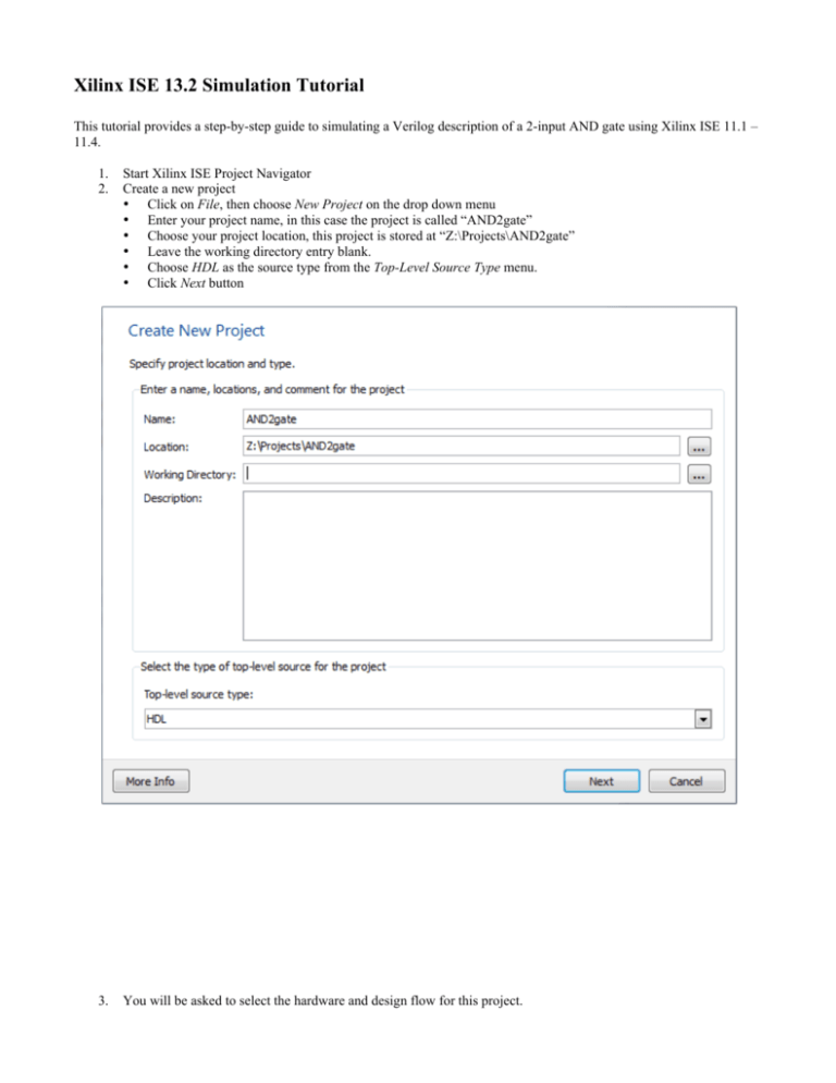
Xilinx ISE 13.2 Simulation Tutorial This tutorial provides a step-by-step guide to simulating a Verilog description of a 2-input AND gate using Xilinx ISE 11.1 – 11.4. 1. 2. Start Xilinx ISE Project Navigator Create a new project • Click on File, then choose New Project on the drop down menu • Enter your project name, in this case the project is called “AND2gate” • Choose your project location, this project is stored at “Z:\Projects\AND2gate” • Leave the working directory entry blank. • Choose HDL as the source type from the Top-Level Source Type menu. • Click Next button 3. You will be asked to select the hardware and design flow for this project. • • • • • • For Family, choose Spartan3E For Device, choose XC3S500E For Package, choose FG320 For Speed, choose -4 For Simulator, choose ISim (VHDL/Verilog) Click Next button 4. A project summary will appear. Click on the Finish button. 5. You now have a project by the name of “AND2gate”. Next you want to specify the files in this project are for behavioral simulation. • Click on Simulation Choose “Simulation” 6. Now we want to add a new file to our project. • Click on Project, choose New Source • Choose Verilog Module as the file type • In the File name: box enter the desired file name, in this case the file is named “and2gate.v” • Click on the Next button 7. You will be asked for the module’s port names/types. You can skip this step and click on the Next button. 8. A project summary will appear. Click on the Finish button. 9. The “and2gate.v” file has been added to your project. “and2gate.v” added to project 10. Click on the and2gate.v tab to show the file contents. You are now ready to specify the and2gate module’s functionality. workspace Click on “and2gate.v” tab 11. Notice that the ISE has already entered a comments sections along with a couple of lines of code for us. • The line “`timescale 1ns/ 1ps” is located at the top of the file. The Verilog language uses dimensionless time units, and these time units are mapped to “real” time units within the simulator. `timescale is used to map to the “real” time values using the statement `timescale <time1> / <time2>, where <time1> indicates the time units associated with the #delay values, and the <time2> indicates the minimum step time used by the simulator. • The and2gate module is also declared using “module and2gate();” and “endmodule”, but the ports are left for us to define. • We finish specifying the functionality of the and2gate module as shown below. `timescale 1ns / 1ps module and2gate(A, B, F); input A, B; output F; reg F; always @ (A, B) begin F <= A & B; end endmodule 12. We also want to add a test bench and again follow Steps 8 – 11 to add “and2gate_tb.v”. Then we add the functionality of the testbench module as shown below. `timescale 1ns / 1ps module and2gate_tb(); reg A_t, B_t; wire F_t; and2gate and2gate_1(A_t, B_t, F_t); initial begin // case 0 A_t<=0; B_t<=0; #1 $display("F_t = %b", F_t); // case 1 A_t<=0; B_t<=1; #1 $display("F_t = %b", F_t); // case 2 A_t<=1; B_t<=0; #1 $display("F_t = %b", F_t); // case 3 A_t<=1; B_t<=1; #1 $display("F_t = %b", F_t); end endmodule 13. After saving both “and2gate.v” and “and2gate_tb.v”, we want to check the syntax of both files. • Expand the ISim Simulator menu, double click on Behavioral Check Syntax • If the syntax was correct, a checkmark appears beside the Check Syntax menu • If the syntax was incorrect, the window at the bottom will list the individual errors. • Expand ISim Simulator menu, double click on Behavioral Check Syntax Any errors will be listed here 14. Now it’s time to simulate the design. • Double-click on the Simulate Behavioral Model icon Double-click on “Simulate Behavioral Model” 15. The ISim Simulator open in a new windows displaying a waveform and run a default simulation for some number of time units. We can now check the and2gate module’s functionality. Further, the $display statements included in the testbench appear in the lower window. $display statements appear here 16. To view the beginning of simulation, click on the Go To Time 0 button. Click on “Go To Time 0” 17. We can now see the simulation waveform for the beginning of our simulation. Click on the Zoom Out button until you see the waveform shown in the image below. Click on “Zoom Out” 18. To control the simulation time, we can restart the simulation and simulate for a specific length of time. Either click on the Restart button or select Restart from the Simulation menu. We will now have an empty waveform. Click on “Restart” 19. To simulate for a specific length of time, enter the desired simulation time and click on the Run for the time specified in the toolbar button. In our case, we want to simulate for 10 ns. Enter the simulation time and click on “Run for…”

