ME 266 SOLID MECHANICS LABORATORY VIRTUAL TENSILE
advertisement
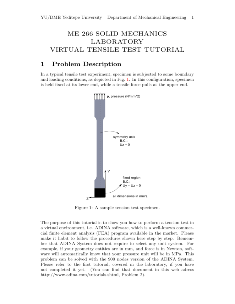
YU/DME Yeditepe University Department of Mechanical Engineering 1 ME 266 SOLID MECHANICS LABORATORY VIRTUAL TENSILE TEST TUTORIAL 1 Problem Description In a typical tensile test experiment, specimen is subjected to some boundary and loading conditions, as depicted in Fig. 1. In this configuration, specimen is held fixed at its lower end, while a tensile force pulls at the upper end. Figure 1: A sample tension test specimen. The purpose of this tutorial is to show you how to perform a tension test in a virtual environment, i.e. ADINA software, which is a well-known commercial finite element analysis (FEA) program available in the market. Please make it habit to follow the procedures shown here step by step. Remember that ADINA System does not require to select any unit system. For example, if your geometry entities are in mm, and force is in Newton, software will automatically know that your pressure unit will be in MPa. This problem can be solved with the 900 nodes version of the ADINA System. Please refer to the first tutorial, covered in the laboratory, if you have not completed it yet. (You can find that document in this web adress http://www.adina.com/tutorials.shtml, Problem 2). 1 PROBLEM DESCRIPTION 1.1 2 Model Control Data Now, let’s adjust some control parameters in this part. Problem heading: Choose Control =⇒ Heading, enter the heading “ADINA Tension Test Tutorial” and click OK. Master degrees of freedom: Choose Control =⇒ Degrees of Freedom, uncheck the X-Translation, X-Rotation, Y-Rotation and Z-Rotation buttons and click OK. (We perform this step because the two-dimensional solid elements that we will use only provide stiffness for the y-translation and z-translation degrees of freedom.) Choose Control =⇒ Time Function, adjust the parameters as indicated in the below figure. Choose Control =⇒ Time step, adjust the parameters as indicated in the below figure. 1 PROBLEM DESCRIPTION 1.2 3 Specimen Geometry (Solid Modeling) Please note that only half of the specimen is modeled due to the symmetry about y− axis at the middle. In addition, model is constructed as a 2 − D problem to benefit from the advantage of the special case “plane stress assumption”, decreasing the computational effort. Here is a diagram showing the key geometry points used in defining this model: To define points, click the Define Points icon , enter the following information into the X2, X3 columns of the table (you can leave the X1 column blank), then click OK. Points 1 2 3 4 5 6 7 8 9 10 11 12 13 14 X2 0 43 50 46 98 105 102 149 149 105 43 0 50 98 X3 0 0 3 -10 3 0 -10 0 7.5 7.5 7.5 7.5 7.5 7.5 The graphics window should look similar to the first picture at the top of the next page: Arc lines: Click the Define Lines icon , add line 1, set the Type to Arc, set P1 to 2, P2 to 3, Center to 4 and click Save. Then add line 2, set P1 to 5, P2 to 6, Center to 7 and click OK. The graphics window should look similar to the second picture at the top of the next page: Surfaces: Click the Define Surfaces icon , add surface 1, make sure that the Type is set to Vertex, then define the following surfaces and click OK. 1 PROBLEM DESCRIPTION 4 (Click Add after defining surfaces 1 and 2.) Surface Number 1 2 3 4 5 Point 1 1 2 3 5 6 Point 2 2 3 5 6 8 Point 3 Point 4 11 12 11 13 14 13 10 14 9 10 To display the geometry point, line and surface numbers, click the Point Labels icon , Line/Edge Labels icon , and Surface/Face Labels icon The graphics windows should look something like this. . 2 MATERIAL PROPERTIES 2 5 Material Properties In this tutorial, we will assume that our specimen is aluminum, and define material properties given in trial part of the below table. However, when you are preparing your report, you will define these properties based on your measurements in the laboratory. Material Properties Young’s Modulus (MPa) Yield Stress (MPa) Strain Hardening Modulus Poisson’s Ratio trial 70000 145 5000 0.3 experiment ? ? ? 0.3 Click the Manage Materials icon , and click the Plastic Blinear button, then click add. In the Define Blinear Elastic-Plastic Material dialog box, add material 1, set the Young’s Modulus to 7E4, the Poisson’s ratio to 0.3, initial yield stress to 145, strain hardening modulus to 5E3, and click OK. Click Close to close the Manage Material Definitions dialog box. 3 3.1 Mesh Generation Element Definitions , add group numElement group: Click the Define Element Groups icon ber 1, set the Type to 2 − D Solid, set the Element Subtype to Plane Stress, set the Default element thickness to 6, and click OK. Subdivision data: In this mesh, we will assign a uniform point size to all points and have the AUI automatically compute the subdivisions. Choose Meshing=⇒Mesh Density=⇒Complete Model, make sure that the “Subdivision Mode” is set to “Use End-Point Sizes” and click OK. Now choose Meshing=⇒Mesh Density=⇒Point Size, set the “Points Defined from” field to “All Geometry Points”, set the Maximum to 1.5 and click OK. The graphics window should look something like this: Element generation: Click the Mesh Surfaces icon , enter 1, 2, 3, 4, 5 in the first three rows of the Surface ] table, change Nodes per Element to 4 LOADS AND BOUNDARY CONDITIONS 6 4 (here, we are saying that hey ADINA, use 4-noded rectangular elements) and click OK. The graphics window should look something like this: 4 4.1 Loads and Boundary Conditions Defining and Applying Boundary Conditions We need two boundary conditions (B.C.), one for specimen fixation and one for modeling symmetry. For the first B.C., choose Model=⇒Boundary Conditions=⇒Apply Fixity on Nodes, and constrain the Y and Z translation of these nodes 362, 391, 420, 449, 478, 507 similar to the below figure. Take a photo of the specimen during the experiment and apply your boundary conditions exactly to the same nodes as seen in your photo to replicate the true experiment conditions. Now apply second B.C. to model symmetry. Click the Apply Fixity icon , and click the Define... button. In the Define Fixity dialog box, add fixity name ZT, check the Z-Translation button and click Save. In the Apply Fixity dialog box, set the “Apply to” field to Lines. To set the fixity for lines 4, 7, 10, 13, 16 to ZT, enter 4, 7, 10, 13, 16 in the first row and column of the table, then move the cursor to the first row, second column, click to display the list, and choose ZT from the drop-down list. Then click OK. 4 LOADS AND BOUNDARY CONDITIONS Click Boundary Plot icon 4.2 7 , to observe applied B.C’s: Defining and Applying Loads Choose Model=⇒Loading=⇒Apply on Node/Elements, set Load Type to displacement, and apply loads (15 mm displacement in the -Y -axis) on these nodes, 89, 118, 147, 176, 205, 234, similar to the below figure. Take a photo of the specimen during the experiment and apply your loads exactly to the same nodes as seen in your photo to replicate the true experiment conditions. Finally, the complete FE model should look similar to the figure at the next page: Generating the ADINA data file, running ADINA, loading the porthole file: First click the Save icon , and save the database to file tension tutorial. To generate the ADINA data file and run ADINA, click the Data File/Solution 5 POST-PROCESSING 8 icon , set the file name to tension tutorial, make sure that the Run Solution button is checked and click Save. 5 Post-processing When ADINA is finished, close all open dialog boxes. Choose Post-Processing from the Program Module drop-down, list and discard all changes. Then click , set the “File type” field to “ADINA-IN Database Files the Open icon (*.idb)”, choose file tension tutorial and click Open. Then click the Open icon , and open porthole file tension tutorial. Now, you are ready for post processing. In this part, we will examine the results, i.e., displacement, stress, at particular locations (model lines and point). Rather than illustrating how to perform these in ADINA (leaving this side to the laboratory), here the report deliverables to be included in virtual part of your tensile test report will be mentioned. Prior to plotting the relevant graphs, you need to define model lines and point as depicted in Fig. 2. 5.1 Stress Contour Plot Obtain a contour plot of the normal stresses in the y−direction over the entire domain. Discuss the stress concentration regions in the plot. 5.2 Line Plot Obtain the variation of normal stress in the y−direction over model lines B and C. Discuss the homogeneity of stress in the gage region. 5 POST-PROCESSING 5.3 9 Element Time History Plot Obtain the y−component of stress and strain at point E as a function of time, and obtain a stress-strain plot for this point. Discuss the similarities and differences between the experimental stressstrain curve and this curve (numerical). 5.4 Force Integration Calculate the resultant force in the y−direction at the end of the 15-mm displacement. (Take the integral of normal stress component over the model line C.) Compare the above with the experimental force at the corresponding instant of displacement. Figure 2: Half of the specimen with model lines and point.
