IJSRD - International Journal for Scientific Research & Development| Vol. 3, Issue 03, 2015 | ISSN (online): 2321-0613
Design of Pneumatic Operated Jack for Four Wheelers
P. S. Borkar1 S. V. Sontakke2 R. R. Dorwe3 A. B. Ganorkar4 S. P. Lokhande5
1,2,3,4,5
Assistant Professor
1,2,3,4,5
P.C.E., Nagpur
Abstract— This fabrication is based on pneumatics which
deals with the study and application of pressurized air to
produce mechanical motion. Pneumatic jack is a fabricated
model which when installed in four wheeler, will ease in the
problems arising in the conventional operated jack. This
fabricated model consists of a small size reciprocating air
compressor which is driven by the battery used in four
wheeler, an air tank to store the compressed air, and a
pneumatic control valve which regulates the air flow and
double acting cylinder used as a jack which performs lifting.
Thus the car is lifted using jack and the problem related to
tyres such as puncture tyres, tyre replacement and wheel
balancing can be resolved with less effort and time.
Keywords: Valves, Cont, conventional operated jack
I. INTRODUCTION
While driving a four wheelers in the way when we faced a
problem related to tyres there is a hectic manual procedure
is used to lift a vehicle i.e., use of manual or hydraulic
operated jack which requires extra human effort and time
i.e., to place a jack in a supportable position then applying
muscular force to screw in the jack for spherical and
transitional motion to lift vehicle. To save this effort and
time we propose a fabricated model based on Pneumatics.
II. INTRODUCTION TO THE PLAN
Although there are available sources of lifting the vehicle
but those mechanisms do not provide the safe, simple and
cost effective method. This project contains unique safety
features which were not provided before.We have made the
project on the pneumatic jack for lifting the four wheelers
i.e. light weight four wheelers especially cars. Now a day we
can see hydraulic jacks are used for the lifting up the
vehicles. And it is very hectic and a long tedious procedure
is used. So we planned an in built pneumatic jack for four
wheelers which is mounted at the center of the of the rear
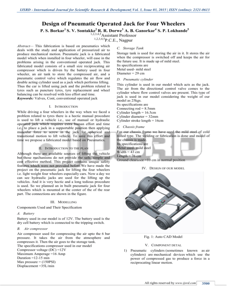
part. The connections are shown in the figure.
C. Storage Tank
Storage tank is used for storing the air in it. It stores the air
when the compressor is switched off and keeps the air for
the future use. It is made up of mild steel.
Its specifications are
Metal used- mild steel
Diameter = 29 cm
D. Pneumatic cylinder
This cylinder is used in our model which acts as the jack.
The air from the directional control valve comes to the
cylinder where flow control valves are present. This type of
jack is used in our model considering the weight of our
model as 25kgs.
Its specifications are
Connecting rod = 8.5mm
Cylinder length = 16.5cm
Cylinder diameter = 32mm
Cylinder stroke length = 16cm
E. Chassis frame
For our chassis frame we have used the mild steel of cold
rolled type. The welding or fabrication is done and model of
the chassis is made.
Its specifications are
Metal used- mild steel
Width = 43 cm
Length = 76 cm
Ground clearance =10 cm in normal position
IV. DESIGN OF OUR MODEL
III. MODELLING
Components Used and Their Specification
A. Battery
Battery used in our model is of 12V. The battery used is the
dry cell battery which is connected to the tripping switch.
B. Air compressor
Air compressor used for compressing the air upto the 6 bar
pressure. It takes the air from the atmosphere and
compresses it. Then the air goes to the storage tank.
The specifications compressor used in our model
Compressor voltage (DC) =12V
Maximum Amperage =16 Amp
Duration =12-15 min
Max pressure = (150PSI)
Displacement =35L/min
Fig. 1: Auto CAD Model
V. COMPONENT DETAL
1) Pneumatic cylinders (sometimes known as air
cylinders) are mechanical devices which use the
power of compressed gas to produce a force in a
reciprocating linear motion.
All rights reserved by www.ijsrd.com
3500
Design of Pneumatic Operated Jack for Four Wheelers
(IJSRD/Vol. 3/Issue 03/2015/872)
Like hydraulic cylinders, something forces
a piston to move in the desired direction. The piston is a disc
or cylinder, and the piston rod transfers the force it develops
to the object to be moved. Engineers sometimes prefer to
use pneumatics because they are quieter, cleaner, and do not
require large amounts of space for fluid storage.
Because the operating fluid is a gas, leakage from a
pneumatic cylinder will not drip out and contaminate the
surroundings, making pneumatics more desirable where
cleanliness is a requirement. For example, in the mechanical
puppets of the Disney Tiki Room, pneumatics is used to
prevent fluid from dripping onto people below the puppets.
Cylinders are linear actuators which convert fluid
power into mechanical power. They are also known as
JACKS or RAMS. Hydraulic cylinders are used at high
pressures and produce large forces and precise movement.
For this reason they are constructed of strong materials such
as steel and designed to withstand large forces.
Because gas is an expansive substance, it is
dangerous to use pneumatic cylinders at high pressures so
they are limited to about 10 bar pressure. Consequently they
are constructed from lighter materials such as aluminium
and brass. Because gas is a compressible substance, the
motion of a pneumatic cylinder is hard to control precisely.
The basic theory for hydraulic and pneumatic cylinders is
otherwise the same
Valve's actuator
Valve's positioner
Valve's body
VI. CALCULATIONS
A. Volume of the Air Stored In the Air Tank
V = πr₂ h
V = 12π (29/2)₂
V= 6605.19 cm3
Or V= 66.05 m3
Where,
V= volume of air
r= radius of the cylinder
h= height of the cylinder
B. Pressure Required Lifting Up the Chassis
Weight of the chassis = 25 kg
25 kg = 245 N
F=Pπ (d12-d22)/4
Where,
F= Load to be lifted
d1= cylinder diameter
d2= cylinder rod diameter
P= pressure required
P =4 F/π (0.0322-0.00852)
P = 327758.0126 Pa
Or P = 327 kPa
Above is the result for the pressure required to lift up the
model by the cylinder.
VII. COMPARISON OF PNEUMATICS WITH HYDRAULICS
Fig. 2: Pneumatic Cylinder
2) Control Valves,Control valves are valves used to
control conditions such as flow, pressure,
temperature, and liquid level by fully or partially
opening or closing in response to signals received
from controllers that compare a "setpoint" to a
"process variable" whose value is provided by
sensors that monitor changes in such conditions.
Control Valve is also termed as the Final Control
Element.
The opening or closing of control valves is usually
done automatically by electrical, hydraulic or pneumatic
actuators. Positioners are used to control the opening or
closing of the actuator based on electric or pneumatic
signals. These control signals, traditionally based on 3-15psi
(0.2-1.0bar), more common now are 4-20mA signals for
industry, 0-10V for HVAC systems, and the introduction of
"Smart" systems, HART, Fieldbus Foundation, and Profibus
being the more common protocols. Some of the control
valves available are Reverse Double-Ported Globe-Style
Valve Body, Three-Way Valve with Balanced Valve Plug,
Flanged Angle-Style Control Body, and Valve Body with
Cage-Style Trim, Balanced Valve Plug, and Soft Seat.
A control valve consists of three main parts in which each
part exist in several types and designs:
Pneumatic jacks work by way of pressurized gas used to
create mechanical motion. Hydraulic jacks, on the other
hand, use liquid to affect motion. Both types of jacks are
available to consumers; however, hydraulic jacks are more
popular for a number of reasons, and pneumatic jacks are
less readily available due to the drawbacks of pneumatic
mechanics. This doesn’t mean that a pneumatic jack is a bad
choice, but rather that a comparison between the two
products is time well spent.
A. Lifespan and Cost
Pneumatic jacks have a lifespan of five to 10 years if the
jack is properly maintained and serviced as necessary.
Hydraulic jacks often last upward of 15 years. The cost of
pneumatic jacks, though, is often lower than the cost of
hydraulic jacks.
B. Efficiency
Pneumatic jacks are more efficient than hydraulics, as air
does not cause the wear and tear of the parts of pneumatics
and hence works for the longer time.
C. Safety issues
Despite the immense capabilities of hydraulics presented in
terms of moving higher loads and in other industrial
utilization, pneumatics is still in wide use today.
Pneumatics is study of mechanical motion caused
by pressurized gases and how this motion can be used to
perform engineering tasks. Pneumatics is used mainly in
mining and general construction works. Pneumatic devices
are used frequently in the dentistry industry across the
All rights reserved by www.ijsrd.com
3501
Design of Pneumatic Operated Jack for Four Wheelers
(IJSRD/Vol. 3/Issue 03/2015/872)
world. On the other hand, hydraulics means use of
pressurized fluids to execute a mechanical task. Hydraulics
is frequently used in the concepts of turbines, dams, and
rivers. Air brakes in buses, air compressors, compressed air
engines, jackhammers, and vacuum pumps are some of the
most commonly used types of mechanical equipment that
are based on pneumatics technology.
VIII. OPERATION OF A PNEUMATIC SYSTEM
In order to affect mechanical motion, pneumatics employs
compression of gases, based on the working principles of
fluid dynamics in the concept of pressure. Any equipment
employing pneumatics uses an interconnecting set of
components: a pneumatic circuit consisting of active
components such as gas compressor, transition lines, air
tanks, hoses, open atmosphere, and passive components.
Compressed air is supplied by the compressor and is
transmitted through a series of hoses. Air flows are
regulated by valves and the pneumatic cylinder transfers the
energy provided by the compressed gas to mechanical
energy. Aside from compressed air, inert gases are also
applied particularly for self-contained systems. Pneumatics
is applied in a wide range in industries, even in mining and
dentistry. The majority of industries use gas pressures of
about 80 to 100 pounds per square inch.
Thus leaks will be of less concern since the
working fluid of pneumatics is air, unlike oil in hydraulics.
Its working fluid is also widely available and most factories
are pre-plumbed for compressed air distribution, hence
pneumatic equipment is easier to set-up. To control the
system, only ON and OFF are used and the system consists
only of standard cylinders and other components, making it
simpler than hydraulics. Pneumatic systems require low
maintenance and have long operating lives. Lastly the
working fluid of the pneumatic system absorbs excessive
force, leading to less frequent damage to equipment.
Compressible gases are also easy to store and safer; no fire
hazard is presented and machines could be made to be
overload safe.
Fig. 4: Actual Model
IX. OTHER ADVANTAGES
Initial cost is less; hydraulics equipment cost as
much as twice the price of pneumatic equipment.
A pneumatic water treatment automation system
reduces the costs of installation and operation
compared with conventional electrical installations.
For opening and closing of underwater valves,
pneumatic systems work well because they can
sustain overload pressure conditions.
Pneumatic actuators also have long life and
perform well with negligible maintenance
requirement throughout their life cycle.
Very suitable for power transmission when
distance of transmission is more.
X. RESULT
From our project the following results came
We can lift the weight of 25 kg at 327 kPa.
Volume of the air can be stored in the storage tank
is 66.05m3.
Pneumatics working fluid is also widely available
and most factories are pre-plumbed for compressed
air distribution, hence pneumatic equipment is
easier to set-up then hydraulics.
To control the system, only ON and OFF are used
and the system consists only of standard cylinders
and other components, making it simpler than
hydraulics.
The working fluid of the pneumatic system absorbs
excessive force, leading to less frequent damage to
equipment.
XI. CONCLUSION
Fig. 3: Pneumatic Drill
Following are the conclusion made from the project:
After completing the project we have come to the
conclusion that pneumatics jacks can act in the
place of hydraulic jacks efficiently. The inbuilt jack
serves as the boon for the cars.
The air required for the operating of the jack is
easily available in the nature.
Cost of the project is not high compared with other
jacks.
As our jack is inbuilt the fatigue is less.
If made in the lot the cost could be less.
It serves better than hydraulic jacks which is used
for lifting up.
All rights reserved by www.ijsrd.com
3502
Design of Pneumatic Operated Jack for Four Wheelers
(IJSRD/Vol. 3/Issue 03/2015/872)
REFERENCES
[1] Mr. S.R. Mujumdar, “Handbook of pneumatic
system”.
[2] Mr. Lev Abramovich, “Handbook of component of
pneumatic”.
[3] Mr. H.Adelman, “Handbook of guidelines for the
use of pneumatic system”.
[4] Tweng-Huang Wang, “Automatic pneumaticHydraulic Jack”, United States Patent, Patent
number- 4,523,743, June 1985
[5] P. S. Rana, P. H. Belge, “Integrated Automated
Jacks for 4- wheelers”, European Journal of
Applied Engineering and Scientific Research,
2012, 1 (4):167-172, ISSN: 2278-0041
[6] William Cox, “Light Talk on Heavy Jacks”, Old
House Journal, July 2001
[7] Muller, Pamela and Thomas L Muller, “Built InPower Jack”, U.S. Patent Number 4, 993, 1991
[8] Parr, Andrew, “Hydraulics and Pneumatics”, A
Technician’s and Engineer’s Guide, 1st Edition,
and Oxford: Butterworth-Heinemann, 1999. Print
[9] N.A. Nagrare, C. A. Padwad, “Integrated
Automated Jacks for 4- wheelers”, European
Journal of Applied Engineering and Scientific
Research, 2012, 1 (4):167-172, ISSN: 2278-0041
[10] Anthony R. Frantoni, “Pneumatic Jack”, United
states Patent, Patent number: US 6,585,231 B1,
July 2003
[11] Clinton Jackson S R, “Pneumatic Vehicle jacking
System”, United States Patent, Patent Number; US
2005/0127343, June 2005
[12] Ikechukwu Celestine Ugwuoke Olawale James
Okegbile and Ibukun Blessing Ikechukwu,
“Development of a Foot Operated Hydraulic Lifter
for Automobile Workshops”, International Journal
of emerging Trends in Engineering and
Development, Issue 4, Volume 2, March 2014
[13] Pierre M Ghobert, Rene Lucien, Yves A Pascal,
“Hydraulic jack”, US Patent; Patent number: US
3661052 A,May 1972
[14] Anthony R. Fratoni, Jr. “Pneumatic jack”, US
Patent, Patent Number- US6585231 B1, July 2003
[15] Stewart W. Getty, “Pneumatic jack”, US Patent,
Patent Number: US4087076 A, May 1978
All rights reserved by www.ijsrd.com
3503

