2501 Dallas Street
Aurora, Colorado 80010
USA
Telephone 303.340.5200
OPERATION AND MAINTENANCE MANUAL
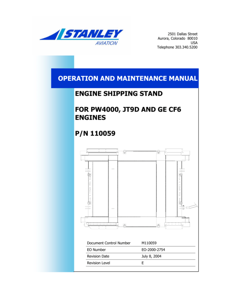
ENGINE SHIPPING STAND
FOR PW4000, JT9D AND GE CF6
ENGINES
P/N 110059
Document Control Number
M110059
EO Number
EO-2000-2754
Revision Date
July 8, 2004
Revision Level
E
STANLEY AVIATION CORPORATION
Operation and Maintenance Manual
ENGINE SHIPPING STAND P/N 110059
RECORD OF REVISIONS
EO#
REVISION
LEVEL
DATE
BY
-/NC-C
NO RECORD
2000-2552
D
MARCH 1, 1999
P. Castricone
2000-2754
E
JULY 8, 2004
P. Nemani
HIGHLIGHTS OF REVISIONS
Revision -/NC-C
No record of changes
Revision D
No record of changes
Revision E
Brought to current format, updating IPL w/latest ACAD drawings
2
STANLEY AVIATION CORPORATION
Operation and Maintenance Manual
ENGINE SHIPPING STAND P/N 110059
Table of Contents
Record of Revisions................................................................................................................ pg. 2
Table of Contents.................................................................................................................... pg. 3
Description ............................................................................................................................. pg. 4
Safety Considerations ............................................................................................................ pg. 5
Specifications and Capabilities ............................................................................................... pg. 5
Operation ............................................................................................................................... pg. 6
Shipping .................................................................................................................................. pg. 6
Storage ................................................................................................................................... pg. 6
Cleaning.................................................................................................................................. pg. 6
Inspection ............................................................................................................................... pg. 7
Minor repairs .......................................................................................................................... pg. 8
Major repairs .......................................................................................................................... pg. 8
Illustrated Parts List .............................................................................................................. pg. 9
110059-501,Top View ................................................................................................ pg. 10
110059-501, Port Side View ...................................................................................... pg. 11
110059-501, End View .............................................................................................. pg. 12
All rights reserved. No part of this handbook may be reproduced or transmitted in any form or by any means,
electronic or mechanical, including photocopying, recording, or by any information storage and retrieval
system, without written permission from Stanley Aviation Corporation.
3
STANLEY AVIATION CORPORATION
Operation and Maintenance Manual
ENGINE SHIPPING STAND P/N 110059
Section 1 - DESCRIPTION
This manual provides maintenance instructions and a parts list for the Stanley Aviation Engine Shipping
Stand, part numbers 110059-501, -507, -509, 601, -606, -701, and -801. This particular model facilitates air
and truck shipping of all Pratt & Whitney JT9D and 4000 engines and General Electric CF6 engines. The
stand has a 90” center-to-center rail system and ships on a standard 96” x 125” pallet.
The Engine Shipping Stand is generally used in conjunction with an engine cradle when transporting any aircraft engine. Although a cradle is designed for engine-specific applications, only the Shipping Stand is discussed in detail herein. See the appropriate Stanley Operation and Maintenance Manual for engine cradle
operation and service instructions and parts lists.
The primary difference between the different versions of the 110059 Shipping Stand is the rail size. All operations discussed herein apply to all versions of the Stanley Aviation 110059 Engine Shipping Stand.
For additional information on this or other aviation ground support applications, contact a Customer Service
Representative at the following address:
S T A N L E Y
A V I A T I O N C O R P O R A T I O N
2501 Dallas Street
Aurora, Colorado 80010 USA
303-340-5200
Fax 303-360-8965
GSE@stanleyaviation.com
4
STANLEY AVIATION CORPORATION
Operation and Maintenance Manual
ENGINE SHIPPING STAND P/N 110059
Section 2 - SAFETY CONSIDERATIONS
•
This equipment is heavy and has moving parts. Whenever such a combination exists, there is the potential for serious injury. Work carefully at all times.
•
Be alert and pay attention when using this equipment. Careless use, or a casual attitude during operation, may lead to an accident.
•
Keep your feet clear of the Shipping Stand during all operations.
•
Keep your hands clear of all pinch points on the Shipping Stand.
•
Pay attention to all warnings that are stenciled on the Shipping Stand. They are there for your safety. Do
not ignore or violate them.
•
Walk around the Shipping Stand; don't climb over it.
•
Never crawl under a Shipping Stand that is loaded.
Section 3 - SPECIFICATIONS AND CAPABILITIES
3.1
Applications
This Shipping Stand is designed specifically for transportation, ground handling, and bootstrapping of
all Pratt & Whitney JT9D and 4000 engines, as well as General Electric CF6 engines.
3.2
Dimensions
Length: -601, -606, -701 and -701 configurations are 178” (452 cm), excluding the towbar. All other
configurations are 173” (439 cm)
Width: 94” (239 cm)
Height: –509 and –701 configurations are 37” (94 cm). All other configurations are 38” (97 cm).
3.3
Capacities
The Stand is designed to hold the weight of the cradle and the compatible engines.
5
STANLEY AVIATION CORPORATION
Operation and Maintenance Manual
ENGINE SHIPPING STAND P/N 110059
Section 4 - OPERATION
For operational characteristics of the Stand-Cradle combination, i.e., for installation and removal of the engine, refer to the Cradle’s Operation and Maintenance Manual and the bootstrapping instructions provided by
the aircraft or engine manufacturer.
Section 5 - SHIPPING
The Shipping Stand may be shipped by any preferred method without special preparation. Position the Stand
casters in the normal towing position. Ground clearance is approximately 7.5” with the system empty, and
6.4” with the system loaded. The –509 and -701 configurations have approximately 1” of additional ground
clearance.
Section 6 - STORAGE
The Shipping Stand requires no special storage treatment, as it has been suitably protected from normal environmental deterioration. For long-term storage, the unit should be stored in a humidity-controlled environment.
Section 7 - CLEANING
7.1
Clean entire assembly with a mild detergent solution followed by a clear water rinse.
7.2
Dry all parts using a clean cloth or low pressure compressed air.
NOTE
DO NOT USE COMPRESSED AIR TO DRY AREAS NEAR
BEARINGS, GEARS, OR OTHER MOVING PARTS.
6
STANLEY AVIATION CORPORATION
Operation and Maintenance Manual
ENGINE SHIPPING STAND P/N 110059
Section 8 - INSPECTION
To ensure efficient and reliable operation, the Stanley Shipping Stand must be maintained through regular
preventive maintenance practices. These practices include inspection, cleaning, and lubrication. All preventive maintenance must be performed at least once every six months. The manufacturer recommends more
frequent maintenance under conditions of heavy service or extreme weather. Replace any parts that do not
meet inspection standards.
Routine inspection should include the following items:
8.1
Clean the Stand per Section 7.
8.2
Inspect all parts for dirt and signs of wear or damage.
8.3
Inspect all structural members for distortion, breaks, cracks, or other signs of damage.
8.4
Jack up the Stand, place blocks or safety stands under it, and inspect the casters:
•
Check for free-running operation and proper treadwear.
•
Check the caster bearings for excessive play or binding. The wheels should spin freely, and
there should by no lateral or axial movement.
•
Check the aft casters for brake actuation and release. Adjust as necessary.
8.5
Inspect load-bearing surfaces and the threads of all bolts for small cuts, scoring, distortion, elongation, or other signs of wear or damage.
8.6
Inspect all bolted parts for looseness and tighten as necessary.
8.7
Inspect the paint and plating for cuts or chips and repair as required per Section 9.2
7
STANLEY AVIATION CORPORATION
Operation and Maintenance Manual
ENGINE SHIPPING STAND P/N 110059
Section 9 - MINOR REPAIRS
9.1
Replace any parts that do not meet inspection requirements and cannot be repaired in the field.
9.2
Minor corrosion and other surface blemishes may be removed using crocus cloth and phosphate ester resistant paint. Unpainted parts may be protected with a thin coating of light oil.
CAUTION
DO NOT paint plated surfaces or aircraft-attaching hardware.
Section 10 - MAJOR REPAIRS
No major repair is possible in the field. This unit must be returned to the manufacturer for overhaul,
proof load testing and recertification following any major damage.
8
STANLEY AVIATION CORPORATION
Operation and Maintenance Manual
ENGINE SHIPPING STAND P/N 110059
Section 11 - ILLUSTRATED PARTS LIST
11.1
How to use this Parts List
Turn to the Assembly Figure and identify the part by location and appearance. Note the Item Number assigned to the illustrated part. Locate the Item Number in the appropriate parts list. The line
entry for that Item Number provides the, Part Number, Description, and Quantity required Per Assembly.
11.2
Units Per Assembly
Quantities specified in the Units Per Assembly column are the total number of each part required for
the indicated assembly, if the part is included in a higher-level assembly. The total quantity required
is a product of the quantities indicated at each level, up to the Top Assembly.
11.3
How to order Replacement Parts
Replacement parts and/or spare parts listed in this manual may be ordered by specifying the Top
Assembly Part Number, the Subassembly Part Number (if any), the Item Number, Description, and
the Quantity Required.
Example:
TOP ASSEMBLY
SUBASSEMBLY
P/N 215030-1 TOWBAR ASSEMBLY
ITEM 20, ADAPTER KIT
Item number
Part number
Description
Quantity Req’d/
Units Per Assembly
4
101715-75
washer
2
In the above example, there are two washers per adapter kit, and one adapter kit per towbar, so to replace
all washers on the adapter kit bolt, a quantity of 2 is specified.
Replacement and/or spare parts may be ordered from:
S T A N L E Y
A V I A T I O N C O R P O R A T I O N
2501 Dallas Street
Aurora, Colorado 80010 USA
303-340-5200
Fax 303-360-8965
GSE@stanleyaviation.com
9
9
STANLEY AVIATION CORPORATION
Operation and Maintenance Manual
ENGINE SHIPPING STAND P/N 110059
S P/N 110059
Section 11 – ILLUSTRATED PARTS LIST (cont’d)
10
STANLEY AVIATION CORPORATION
Operation and Maintenance Manual
ENGINE SHIPPING STAND P/N 110059
S P/N 110059
Section 11 - ILLUSTRATED PARTS LIST (cont’d)
11
STANLEY AVIATION CORPORATION
Operation and Maintenance Manual
ENGINE SHIPPING STAND P/N 110059
Section 11 – ILLUSTRATED PARTS LIST (cont’d)
S P/N 110059
12
STANLEY AVIATION CORPORATION
Operation and Maintenance Manual
ENGINE SHIPPING STAND P/N 110059
Section 11 – ILLUSTRATED PARTS LIST (cont’d)
24
24
24
24
24
24
24
20
102515-200 BOLT
18
18
18
18
18
18
18
19
102801-1
TIE DOWN RING
2
2
2
2
2
2
2
18
150096-3
FILLER
2
2
2
2
2
2
2
17
150096-1
FILLER
4
4
4
4
4
4
4
16
102489-2
DRIVE SCREW
1
1
1
1
1
1
1
15
102001-1
NAME PLATE
120
120
120
120
120
120
120
14
103109-50 LOCK WASHER
96
96
96
96
96
96
96
13
-
-
-
2
-
2
-
9
112602-1
ALUMINUM RAIL
-
2
-
-
-
-
-
8
112601-1
ALUMINUM RAIL
2
-
-
-
2
-
2
7
112603-1
ALUMINUM RAIL
12
12
12
12
12
12
12
6
2
2
2
2
2
2
2
5
150086-1
AFT LOWER MT
1
1
1
1
1
1
1
4
150093-1
AFT UPPER MT LEFT
1
1
1
1
1
1
1
3
150092-1
FWD UPPER MT LEFT
2
2
2
2
2
2
2
2
150081-1
FWD LOWER MT
1
1
1
1
1
1
1
1
150300-1
BASE WELDMENT
101895-125 BOLT
110407-104 SHOCK MT
110059
-501
-507
-509
-601
-606
QUANTITY REQUIRED
-701
-801
ITEM
NO.
PART NO.
STANDARD ASSEMBLY
DESCRIPTION
13
STANLEY AVIATION CORPORATION
Operation and Maintenance Manual
ENGINE SHIPPING STAND P/N 110059
Section 11 – ILLUSTRATED PARTS LIST (cont’d)
6
6
6
6
6
6
6
41
102892-1
-
-
(4)
-
-
(4)
-
40
110059-40 SPACER
2
2
2
2
2
2
-
38
101872-100 CASTLE NUT
2
2
2
2
2
2
-
37
1
1
1
1
1
1
-
36
16
16
16
16
16
16
-
35
101897-250 BOLT
32
32
32
32
32
32
-
34
101715-62 FLAT WASHER
16
16
16
16
16
16
-
33
101876-62 LOCK NUT
4
4
4
4
4
4
-
32
101899-725 BOLT
4
4
4
4
4
4
-
31
101876-88 CASTLE NUT
4
4
4
4
4
4
-
30
101715-88 FLAT WASHER
4
4
4
4
4
4
-
29
110120-14-6 T-HANDLE PIN
2
2
2
2
2
2
-
28
103846-4
CASTER W/ BRAKE
2
2
2
2
2
2
-
27
103846-3
CASTER W/O BRAKE
4
4
(4)
4
4
(4)
-
26
110100-2
CASTER CARRIER
2
2
2
2
2
2
2
25
110397-41 AFT RAIL PLATE
2
2
2
2
2
2
2
24
110397-40 FWD RAIL PLATE
-501
-507
-509
-601
-606
-701
-801
ITEM
NO.
QUANTITY REQUIRED
SAFETY PIN
101905-450D BOLT
110087-1
PART NO.
TOW BAR
DESCRIPTION
14
STANLEY AVIATION CORPORATION
Operation and Maintenance Manual
ENGINE SHIPPING STAND P/N 110059
Section 11 – ILLUSTRATED PARTS LIST (cont’d)
2
2
2
2
2
2
2
69
150082-7
SPACER
2
2
2
2
2
2
2
68
150082-5
SPACER
-
-
4
-
-
4
-
67
110100-27 CASTER CARRIER
8
8
8
8
8
8
8
66
110100-5
BRACKET
1
1
1
1
1
1
1
58
150093-2
AFT UPPER MT RIGHT
1
1
1
1
1
1
1
57
150092-2
FWD UPPER MT RIGHT
-
-
(16)
-
-
(16)
-
50
-
-
1
-
-
-
-
49
-
-
2
-
-
-
-
48
-
-
2
-
-
-
-
46
112605-1
4
4
4
4
4
4
4
45
100059-27 SPRING PIN
4
4
4
4
4
4
4
44
100048-15 SPRING
4
4
4
4
4
4
4
43
112604-1
6
6
6
6
6
6
6
42
101809-09 LANYARD
-501
-507
-509
-601
-606
-701
-801
ITEM
NO.
QUANTITY REQUIRED
101897-350 BOLT
111551-1
BUMPER
104036-125 BOLT
PART NO.
ALUMINUM RAIL
STOP PIN
DESCRIPTION
15

