Brayton Cycle
advertisement
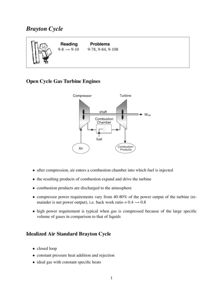
Brayton Cycle Reading 9-8 → 9-10 Problems 9-78, 9-84, 9-108 Open Cycle Gas Turbine Engines • after compression, air enters a combustion chamber into which fuel is injected • the resulting products of combustion expand and drive the turbine • combustion products are discharged to the atmosphere • compressor power requirements vary from 40-80% of the power output of the turbine (remainder is net power output), i.e. back work ratio = 0.4 → 0.8 • high power requirement is typical when gas is compressed because of the large specific volume of gases in comparison to that of liquids Idealized Air Standard Brayton Cycle • closed loop • constant pressure heat addition and rejection • ideal gas with constant specific heats 1 Brayton Cycle Efficiency The Brayton cycle efficiency can be written as η = 1 − (rp )(1−k)/k where we define the pressure ratio as: rp = P2 P1 = P3 P4 2 Maximum Pressure Ratio Given that the maximum and minimum temperature can be prescribed for the Brayton cycle, a change in the pressure ratio can result in a change in the work output from the cycle. The maximum temperature in the cycle (T3 ) is limited by metallurgical conditions because the turbine blades cannot sustain temperatures above 1300 K. Higher temperatures (up to 1600 K can be obtained with ceramic turbine blades). The minimum temperature is set by the air temperature at the inlet to the engine. 3 Brayton Cycle with Reheat • T3 is limited due to metallurgical constraints • excess air is extracted and fed into a second stage combustor and turbine • turbine outlet temperature is increased with reheat (T6 > T4 ), therefore potential for regeneration is enhanced • when reheat and regeneration are used together the thermal efficiency can increase significantly 4 Compression with Intercooling • the work required to compress in a steady flow device can be reduced by compressing in stages • cooling the gas reduces the specific volume and in turn the work required for compression • by itself compression with intercooling does not provide a significant increase in the efficiency of a gas turbine because the temperature at the combustor inlet would require additional heat transfer to achieve the desired turbine inlet temperature • but the lower temperature at the compressor exit enhances the potential for regeneration i.e. a larger ΔT across the heat exchanger 5 Brayton Cycle with Regeneration • a regenerator (heat exchanger) is used to reduce the fuel consumption to provide the required Q̇H • the efficiency with a regenerator can be determined as: η= Ẇnet Q̇H = 1− Q̇L Q̇H 6 = 1− = 1− = 1− cp (T6 − T1 ) cp (T3 − T5 ) cp (T6 − T1 ) cp (T3 − T5 ) ⇒ (f or a real regenerator) ⇒ (f or an ideal regenerator) cp (T2 − T1 ) cp (T3 − T4 ) and η =1− Tmin Tmax (rp )(k−1)/k • for a given Tmin/Tmax , the use of a regenerator above a certain rp will result in a reduction of η with an ideal regenerator without a regenerator better without a regenerator better with a regenerator T1 / T3 = 0.2 T1 / T3 = 0.25 T1 / T3 = 0.3 r p, cr rp 7 Regenerator Effectiveness = Q̇reg,actual Q̇reg,ideal = h5 − h2 h5 − h2 = h5 − h2 h4 − h2 = T5 − T2 T4 − T2 Typical values of effectiveness are ≤ 0.7 Repeated intercooling, reheating and regeneration will provide a system that approximates the TL . Ericsson Cycle which has Carnot efficiency η = 1 − TH Brayton Cycle With Intercooling, Reheating and Regeneration 8 T Tmax Q H, R QH 7s 9s Q reg Q reg 4s 2s QL Tmin Q L, I s Compressor and Turbine Efficiencies Isentropic Efficiencies (1) ηcomp = (2) ηturb = (3) ηcycle = h2,s − h1 h2 − h1 h3 − h4 h3 − h4,s Wnet QH = = = cp (T2,s − T1 ) cp (T2 − T1 ) cp (T3 − T4 ) cp (T3 − T4,s ) QH − QL QH =1− QL QH =1− cp (T4 − T1 ) cp (T3 − T2 ) Given the turbine and compressor efficiencies and the maximum (T3 ) and the minimum (T1 ) temperatures in the process, find the cycle efficiency (ηcycle ). (4) Calculate T2s from the isentropic relationship, T2,s T1 = P2 (k−1)/k P1 . Get T2 from (1). (5) Do the same for T4 using (2) and the isentropic relationship. (6) substitute T2 and T4 in (3) to find the cycle efficiency. 9

