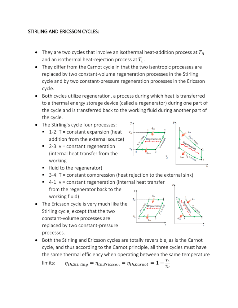
STIRLING AND ERICSSON CYCLES: • They are two cycles that involve an isothermal heat-addition process at 𝑇𝑇𝐻𝐻 and an isothermal heat-rejection process at 𝑇𝑇𝐿𝐿 . • They differ from the Carnot cycle in that the two isentropic processes are replaced by two constant-volume regeneration processes in the Stirling cycle and by two constant-pressure regeneration processes in the Ericsson cycle. • Both cycles utilize regeneration, a process during which heat is transferred to a thermal energy storage device (called a regenerator) during one part of the cycle and is transferred back to the working fluid during another part of the cycle. • The Stirling’s cycle four processes: 1-2: T = constant expansion (heat addition from the external source) 2-3: v = constant regeneration (internal heat transfer from the working fluid to the regenerator) 3-4: T = constant compression (heat rejection to the external sink) 4-1: v = constant regeneration (internal heat transfer from the regenerator back to the working fluid) • The Ericsson cycle is very much like the Stirling cycle, except that the two constant-volume processes are replaced by two constant-pressure processes. • Both the Stirling and Ericsson cycles are totally reversible, as is the Carnot cycle, and thus according to the Carnot principle, all three cycles must have the same thermal efficiency when operating between the same temperature limits: 𝜂𝜂𝑡𝑡ℎ,𝑆𝑆𝑆𝑆𝑆𝑆𝑆𝑆𝑆𝑆𝑆𝑆𝑆𝑆𝑆𝑆 = 𝜂𝜂𝑡𝑡ℎ,𝐸𝐸𝐸𝐸𝐸𝐸𝐸𝐸𝐸𝐸𝐸𝐸𝐸𝐸𝐸𝐸 = 𝜂𝜂𝑡𝑡ℎ,𝐶𝐶𝐶𝐶𝐶𝐶𝐶𝐶𝐶𝐶𝐶𝐶 = 1 − 𝑇𝑇𝐿𝐿 𝑇𝑇𝐻𝐻 • Stirling and Ericsson cycles are difficult to achieve in practice because they involve heat transfer through a differential temperature difference in all components including the regenerator. This would require providing infinitely large surface areas for heat transfer or allowing an infinitely long time for the process. Neither is practical. • Both the Stirling and the Ericsson engines are external combustion engines. That is, the fuel in these engines is burned outside the cylinder which offers several advantages. A variety of fuels can be used as a source of thermal energy. There is more time for combustion, and thus the combustion process is more complete, which means less air pollution and more energy extraction from the fuel. These engines operate on closed cycles, and thus a working fluid that has the most desirable characteristics (stable, chemically inert, high thermal conductivity) can be utilized as the working fluid. Gas Turbine Power Plants: Gas turbines may operate on an open or closed basis and the open gas turbine is more commonly used. The open mode gas turbine is an internal combustion power plant and it operates as follows: • Air is continuously drawn into the compressor where it is compressed to a high pressure. • Air then enters the combustion chamber (combustor) where it mixes with fuel and combustion occurs. • Combustion products exit at elevated temperature and pressure. • Combustion products expand through the turbine and then are discharged to the surroundings. The closed gas turbine operates as follows: • A gas circulates through four components: turbine, compressor, and two heat exchangers at higher and lower operating temperatures, respectively. • The turbine and compressor play the same roles as in the open gas turbine. • As the gas passes through the highertemperature heat exchanger, it receives energy by heat transfer from an external source. • The thermodynamic cycle is completed by heat transfer to the surroundings as the gas passes through the lowertemperature heat exchanger. To conduct elementary analyses of open gas turbine power plants, simplifications are required. So an air-standard analysis assumptions are used for that simplification. Air-Standard Brayton Cycle: Brayton’s cycle’s processes: • At state 1, air is drawn into the compressor from the surroundings. • Process 1-2: the air is compressed from state 1 to state 2. • Process 2-3: The temperature rise that would be achieved in the actual power plant with combustion is realized here by heat transfer, 𝑄𝑄̇𝑖𝑖𝑖𝑖 . • Process 3-4: The high-pressure, high-temperature air expands through the turbine. The turbine drives the compressor and develops net power, 𝑊𝑊̇𝑐𝑐𝑐𝑐𝑐𝑐𝑐𝑐𝑐𝑐 . • Air returns to the surroundings at state 4 with a temperature typically much greater than at state 1 and after interacting with the surroundings, each unit of mass returns to the same condition as the air entering at state 1, thereby completing a thermodynamic cycle. • We imagine process 4-1 being achieved by a heat exchanger. • Cycle 1-2-3-4-1 is called the Brayton cycle. The compressor pressure ratio, p2/p1, is a key Brayton cycle operating parameter. Analyzing each component as a control volume at steady state, assuming the compressor and turbine operate adiabatically, and neglecting kinetic and potential energy effects: 𝑊𝑊̇𝑡𝑡 𝑚𝑚̇ 𝑊𝑊̇𝑐𝑐 𝑚𝑚̇ 𝑄𝑄̇𝑖𝑖𝑖𝑖 = ℎ3 − ℎ 4 = ℎ2 − ℎ1 The thermal efficiency is: 𝜂𝜂 = 𝑚𝑚̇ 𝑊𝑊̇𝑡𝑡 /𝑚𝑚̇−𝑊𝑊̇𝑐𝑐 /𝑚𝑚̇ 𝑄𝑄̇𝑖𝑖𝑖𝑖 /𝑚𝑚̇ The back work ratio is: 𝑏𝑏𝑏𝑏𝑏𝑏 = 𝑊𝑊̇𝑐𝑐 /𝑚𝑚̇ 𝑊𝑊̇𝑡𝑡 /𝑚𝑚̇ = 𝑄𝑄̇𝑜𝑜𝑜𝑜𝑜𝑜 = 𝑚𝑚̇ (ℎ3 −ℎ4 )−(ℎ2 −ℎ1 ) ℎ2 −ℎ1 ℎ3 −ℎ2 = ℎ3 − ℎ 2 = ℎ4 − ℎ1 ℎ3 −ℎ4 Note that a relatively large portion of the work developed by the turbine is required to drive the compressor. For gas turbines, back work ratios range from 20% to 80%. The ideal Brayton cycle consists of two isentropic processes alternated with two isobaric processes. In this respect, the ideal Brayton cycle is in harmony with the ideal Rankine cycle, which also consists of two isentropic processes alternated with two isobaric processes Ideal Air-Standard Brayton Cycle: The ideal air-standard Brayton cycle consists of four internally reversible processes: • Process1-2: Isentropic compression of air flowing through the compressor. • Process 2-3: Heat transfer to the air as it flows at constant pressure through the higher-temperature heat exchanger. • Process 3-4: Isentropic expansion of the air through the turbine. • Process 4-1: Heat transfer from the air as it flows at constant pressure through the lower-temperature heat exchanger. On the p-v diagram, the work per unit of mass flowing is –∫vdp. Thus on a per unit of mass flowing basis, • Area 1-2-a-b-1 represents the compressor work input. • Area 3-4-b-a-3 represents the turbine work output. • Enclosed area 1-2-3-4-1 represents the net work developed. On the T-s diagram, the heat transfer per unit of mass flowing is ∫Tds. Thus, on a per unit of mass flowing basis, • Area 2-3-a-b-2 represents the heat added. • Area 4-1-b-a-4 represents the heat rejected. • Enclosed area 1-2-3-4-1 represents the net heat added or equivalently, the net work developed. Effects of Compressor Pressure Ratio on Brayton Cycle Performance: • Increasing the compressor pressure ratio from p2/p1 to p2′/p1 changes the cycle from 1-2-3-4-1 to 1-2′-3′-4-1. Since the average temperature of heat addition is greater in cycle 1-2′-3′-4-1, and both cycles have the same heat rejection process, cycle 1-2′-3′-41 has the greater thermal efficiency. • Accordingly, the Brayton cycle thermal efficiency increases as the compressor pressure ratio increases. • The turbine inlet temperature also increases with increasing compressor ratio – from T3 to T3′. However, there is a limit on the maximum temperature at the turbine inlet imposed by metallurgical considerations of the turbine blades. Considering the effect of increasing compressor pressure ratio on Brayton cycle performance when the turbine inlet temperature is held constant: This is the T-s diagrams of two ideal Brayton cycles having the same turbine inlet temperature but different compressor pressure ratios. • Cycle A has the greater compressor pressure ratio and thus the greater thermal efficiency. • Cycle B has the larger enclosed area and thus the greater net work developed per unit of mass flow. • For Cycle A to develop the same net power as Cycle B, a larger mass flow rate would be required and this might dictate a larger system. Accordingly, for turbine-powered vehicles, where size and weight are constrained, it may be desirable to operate near the compressor pressure ratio for greater net work per unit of mass flow and not the pressure ratio for greater thermal efficiency. Gas Turbine Power Plant Irreversibility: The most significant irreversibility by far is the irreversibility of combustion. Irreversibilities related to flow through the turbine and compressor also significantly impact gas turbine performance. They act to: • decrease the work developed by the turbine and • increase the work required by the compressor, • thereby decreasing the net work of the power plant. Isentropic turbine efficiency: 𝜂𝜂𝑡𝑡 = (𝑊𝑊̇𝑡𝑡 /𝑚𝑚̇)𝑎𝑎 (ℎ3 − ℎ4𝑎𝑎 ) = (𝑊𝑊̇𝑡𝑡 /𝑚𝑚̇)𝑠𝑠 (ℎ3 − ℎ4𝑠𝑠 ) Isentropic compressor efficiency: (𝑊𝑊̇𝑐𝑐 /𝑚𝑚̇)𝑠𝑠 (ℎ2𝑠𝑠 − ℎ1 ) 𝜂𝜂𝑐𝑐 = = (𝑊𝑊̇𝑐𝑐 /𝑚𝑚̇)𝑎𝑎 (ℎ2𝑎𝑎 − ℎ1 ) Gas Turbine Power Plant Loss: The exhaust gas temperature of a simple gas turbine is typically well above the ambient temperature. Thus, the exhaust gas has considerable thermodynamic utility that would be irrevocably lost were the gas discharged directly to the ambient. Regenerative gas turbines aim to avoid such a significant loss by using the hot exhaust gas cost-effectively. The hot turbine exhaust can be utilized with a preheater called a regenerator. • The regenerator allows air exiting the compressor to be preheated, process 2-x, as the turbine exhaust gas cools, process 4-y. • Preheating reduces the heat added per unit of mass flowing (and thus the amount of fuel that must be burned): With regeneration: Without regeneration: 𝑄𝑄̇𝑖𝑖𝑖𝑖 𝑚𝑚̇ 𝑄𝑄̇𝑖𝑖𝑖𝑖 𝑚𝑚̇ = ℎ3 − ℎ𝑥𝑥 = ℎ3 − ℎ 2 • The net work per unit of mass flowing is not altered with the inclusion of a regenerator. Accordingly, since the heat added is reduced, thermal efficiency increases. • The regenerator effectiveness is defined as the ratio of the actual enthalpy increase of the air flowing through the cold side of the regenerator, hx – h2, to the maximum theoretical enthalpy increase, h4 – h2. :𝜂𝜂𝑟𝑟𝑟𝑟𝑟𝑟 = ℎ𝑥𝑥 −ℎ2 ℎ4 −ℎ2 • In practice, regenerator effectiveness values range from 60-80%, approximately. Thus, the temperature Tx at the combustor inlet is invariably below the temperature T4 at the turbine exit. • Selection of a regenerator is largely an economic decision. With regeneration less fuel is consumed by the combustor but another component, the regenerator, is required. When considering use of a regenerator, the trade-off between fuel savings and regenerator cost must be weighed.
