advanced search
Products
Cables
PC Terminal Emulator Cables, RJ-45 8-pin to DB-9
• device servers
• terminal servers
• console
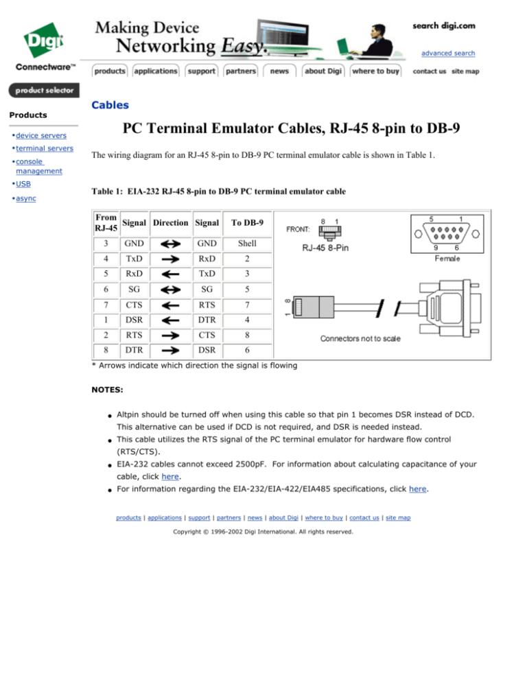
The wiring diagram for an RJ-45 8-pin to DB-9 PC terminal emulator cable is shown in Table 1.
management
• USB
• async
Table 1: EIA-232 RJ-45 8-pin to DB-9 PC terminal emulator cable
From
Signal Direction Signal
RJ-45
To DB-9
3
GND
GND
Shell
4
TxD
RxD
2
5
RxD
TxD
3
6
SG
SG
5
7
CTS
RTS
7
1
DSR
DTR
4
2
RTS
CTS
8
8
DTR
DSR
6
* Arrows indicate which direction the signal is flowing
NOTES:
●
Altpin should be turned off when using this cable so that pin 1 becomes DSR instead of DCD.
This alternative can be used if DCD is not required, and DSR is needed instead.
●
This cable utilizes the RTS signal of the PC terminal emulator for hardware flow control
(RTS/CTS).
●
EIA-232 cables cannot exceed 2500pF. For information about calculating capacitance of your
cable, click here.
●
For information regarding the EIA-232/EIA-422/EIA485 specifications, click here.
products | applications | support | partners | news | about Digi | where to buy | contact us | site map
Copyright © 1996-2002 Digi International. All rights reserved.


