Landen Bowen ME 581 Project Proposal My current research
advertisement
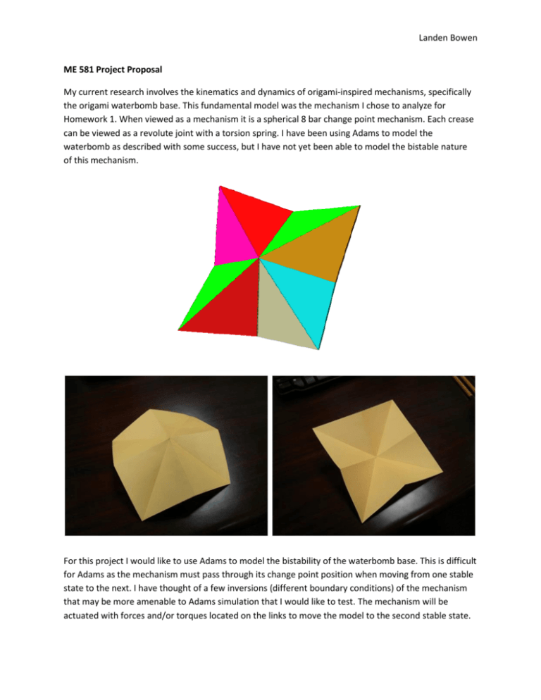
Landen Bowen ME 581 Project Proposal My current research involves the kinematics and dynamics of origami-inspired mechanisms, specifically the origami waterbomb base. This fundamental model was the mechanism I chose to analyze for Homework 1. When viewed as a mechanism it is a spherical 8 bar change point mechanism. Each crease can be viewed as a revolute joint with a torsion spring. I have been using Adams to model the waterbomb as described with some success, but I have not yet been able to model the bistable nature of this mechanism. For this project I would like to use Adams to model the bistability of the waterbomb base. This is difficult for Adams as the mechanism must pass through its change point position when moving from one stable state to the next. I have thought of a few inversions (different boundary conditions) of the mechanism that may be more amenable to Adams simulation that I would like to test. The mechanism will be actuated with forces and/or torques located on the links to move the model to the second stable state. Devon Boyd-ME 581 project Proposal I will digitize a patent for a convertible top mechanism to determine the length of the links. I will then analyze the mechanism using Working Model. The mechanism to be evaluated is the following: Katie Briggs ME 581 Project Proposal Feb 21, 2014 ME 581 Final Project Proposal Recent advancements with computer vision, path planning, and spatial awareness of autonomous vehicles has created interest in having robotic systems facilitate elementary tasks. A specific application consists of robotic vehicle refueling. Vehicle refueling is a daily necessity, and can become quite difficult in remote areas, areas with rough terrain, or harsh environments where human exposure must be limited. This concept also extends to military applications in high risk environments where the opportunity to stop and refuel is minimal. For this project I wish to study the motion of a 4 degree of freedom robotic arm moving along a trajectory necessary to conduct a refueling task. For this task I will calculate both the forward and inverse kinematics of the robotic arm. I will then investigate the standard orientation of a gas tank, and its rough geometry, (height, depth required to successfully mount a tube in the tank). Once this geometry is found, I plan to formulate the trajectory required for the end effector to travel along an axis to place a refueling tube in a gas tank. I will then program the required joint angles and end effector path into a ROS model of the robotic arm to simulate that trajectory movement. The movement will be controlled by a built in PID controller within ROS. I would like to show the ROS simulation, supporting graphs, and derivations as part of my final presentation. Joe Calogero ME581 Project Proposal 16 February 2014 Rigid-Link Dynamic Model of a Bend and Sweep Compliant Mechanism with Non-Linear Stiffness My research is under Dr. Frecker in compliant mechanisms for ornithopter wings. I am continuing research on bend and sweep compliant-aided compliant mechanisms with non-linear stiffness in the upstroke and downstroke positions. In 2013, Yashwanth Tummala created a rigid-link dynamic model of the compliant mechanisms. It works for a variable number of elements, simulating the compliant joints as non-linear torsional springs, and estimates the error in position as compared to a digitized image of a bird flapping its wings. The model, however, is limited to the bending direction and only one digitzed image. I would like to continue his model, incorporating sweep deflection and multiple digitized images. The end result allows an optimization of where to place the elements, determine the error between the mechanism and actual flapping in both bending and sweep deflection, and give further insight to the required stiffnesses of the elements. Page 1 of 1 Adrienne Crivaro Jessica Menold Catapult Design For the final project we will build a trebuchet mechanism to launch ping pong balls. We will then conduct a motion study of the design using Solidworks, and compare it to an analytic study. This data will help position the device so the launched ping pong ball always hits its target. ME 581 Project Proposal Naman Sandeep Kothari Tanmay Mathur VRS Harsha Teja Garimella Title:Gripping Mechanism: Design, Analysis and fabrication Executive Summary Gripping mechanisms find a wide range of applications in industrial automation, prosthetics and is a very common mechanism in complex robots. Project Goals 1. Design of Mechanism Two congruent four bar linkages driven by drivers rotating in opposite directions. The objective is to grip a given object. Modifications at the end point of links 2 and 2’ can be made to grip objects of different material and shapes. 3 2 4 OBJECT 1 1’ 4’ 3’ 2’ Link 2 and link 2’ are rigidly attached to gears driven by a motor- so that they rotate in opposite directions always. 2. Analysis The lengths of links and angles between them have to designed such that the gripping force is maximized for a given object. The transmission angle for maximum force transfer will be evaluated. Kinematic and dynamic analysis of linkages and the point of gripping will be done Finally we’ll analyze the mechanism for gripping a given object with a given force and plot motor torque vs. transmission angle as a design standard. Modelling and motion study using SolidWorks. Forces between the gear pair are not analyzed and both are treated as drivers with dependent angular speeds (in this case equal angular speeds). 3. Fabrication Finally, fabrication of the mechanism using the above design standards will be done. ME 581 (Simulation of Mechanical Systems) Scott Gift Final Project Proposal 2014-02-21 For the final project I would like to design and build the system shown in Figure 1. This system will include 4 servos and a 3-axis accelerometer. The accelerometer will be used as a reference to keep the middle platform level when the ground tilts as shown in Figure 2. The topics covered in this class will be used to calculate the servo angels in real time to accomplish this. For this project, only the 2D case will be determined. A computer and microcontroller will be used to control the servos and read the accelerometer. Software will be written for the computer and the microcontroller. Fabrication of the system’s parts will be conducted in my home workshop. Figure 1 - On Level Ground Figure 2 - Platform is Level on Tilted Ground ME 581 - Spring 2014 – Project Proposal Name _Jeff Irwin_______________________ Who: Jeff Irwin What: Simulation of a Klann linkage using Haug’s method Why: For thousands of years, the transportation mechanism of choice has been wheeled vehicles. Many alternatives exist, such as tracked vehicles. A prominent limitation of these types of vehicles is that they are unable to surmount obstacles. Walking vehicles do not have this limitation, however they may require a large number of actuators and a complex control system. The Klann linkage is a simple walking vehicle that requires only a single link driven at constant angular velocity to transmit full quadrapedal motion to all of its legs. How: Though the entire linkage consists of 19 links, each leg is made up of only 6 links. The kinematics of one leg could feasibly be simulated using Haug’s method. The symmetry of the linkage could then be used to model all 4 legs without assembling a larger Jacobian. With a collision detection algorithm, an animation could be produced of the linkage walking along a surface. If time allows, a dynamic analysis could be performed and the lengths of each link could be optimized for efficient walking. The only resource needed to complete this project is a computer equipped with MATLAB or a similar programming language. Table 1. Timeline of project Task Single leg kinematic simulation Figure 1. A Klann linkage prototype with the driving gear in the center [Wikipedia] Duration (weeks) 3–4 Four leg walking kinematic simulation 3–5 Dynamic analysis and optimization 0–3 Total 9 ME 581 Project Proposal Controls Analysis with LabView Who: Katherine Leshkow What: I would like to perform a controls analysis of a planar mechanism using LabView. The mechanism will first be modeled as a mass-spring-damper system. The equations of motion will be determined using the mass-spring-damper diagram. Then, LabView will be utilized to perform a controls analysis. The analysis will consist of various methods including, but not limited to, root locus and bode plots. The main goal of this project is to learn how to perform a controls analysis utilizing LabView. Why: Control systems are used for creating a desired output. These outputs include a wide range of applications such as power amplification and remote control. Thus, an in-depth knowledge of how to analyze a control system may prove invaluable. In addition, LabView is a broad, powerful tool. By focusing my project on LabView’s Control Design and Simulation Module I will be able to develop a better understanding of just one of the capabilities of this expansive software. How/Resources: Access to LabView’s Control Design and Simulation Module Sam Masters Justin Wager Construction of Three-Dimensional Passive-Dynamic Walkers in OpenSim A passive-dynamic walker (PDW) is a motor-free, bipedal walking mechanism used for examining human gait. Passive-dynamic walkers consist of linked rigid bodies that are anthropometrically similar to the human body. The mechanical energy of PDWs is supplied by gravitational potential energy as the PDW moves down a slight incline. Insights into the kinematics of human walking are often gained from the construction and study of these mechanisms. We propose constructing a computer model of a threedimensional passive walker using MATLAB. The forward dynamic simulation will be implemented using OpenSim. Three PDW models will be constructed. The first PDW will consist of five rigid bodies connected via revolute joints (two shanks, two thighs, and one pelvis). The second PDW will consist of the same rigid bodies with the addition of a round foot connected the end of each shank. Torsional springs will be added to the second PDW’s knee and hip joint to comprise the third walker. We will compare the kinematics of each PDW to typical human gait kinematics. Step-to-step variability will also be assessed by the quantification of step width, step length, and step period. To examine the effects of the rounded feet and torsional springs, the models will be compared to each other to highlight differences in kinematics and kinetics. Passive-Dynamic Walker from OpenSim Tutorial. Kevin McGough Preliminary Project Proposal: Peaucellier-Lipkin Linkage The Peaucellier-Lipkin linkage uses rotation of the input link to create straight line motion of a point. In the above figure, the input link is shown as the solid blue line. The point that follows a straight line path (grey dashed line) is shown as the red dot coincident with two red links. Basic constraints for the mechanism are that the length of the input link is the same as the distance between the two ground pin joints, the two green links attached to one of the ground pin joints are of equal length, and the four red links are of equal length. This linkage is unique because it was the first linkage to transform at rotary input into a straight line output. Interest in studying this mechanism stems from industrial experience where the goal was to design grippers that would grip cylindrical objects of various diameters without the center of the grippers moving out of alignment with the centerline of the cylindrical objects. Additionally, the grippers were to be used in a mechanism/system present in medical procedure operating rooms where the system cannot create dust and has high reliability. A gripper mechanism using the Peaucellier-Lipkin linkage will meet both of these criteria because the pin points of the mechanism will create less dust and be more reliable compared to gripper mechanisms using typical rack and pinion combinations. A proper analysis of this mechanism should consists of position, velocity, and acceleration analyses of the pin joints and links as the input link rotates through its extreme positions. Additionally, it would be desirable to study the forces that the output pin joint can exert because this linkage will be used for grippers. Performing these analyses will provide a high-level understanding of the mechanism so that its behavior can be compared with desired performance criteria. Cesar Moreno ME 581 Project Proposal For my project I would like to take my submission for Hw01 and analyze it further through what is learned within this course. I would also like to build this in real life to see what differences I can see between calculated predictions and actual experimentation. Alex Punzi M E 581 Project Proposal For my M E 581 final project, I will write a report on the inner workings of a clock, with a focus on various escapement mechanisms. I have always been interested in how a clock works but have never had the opportunity to fully investigate it. I became even more interested after completing the second homework assignment for this class, a biography about John Harrison, who was a very famous clock maker. The most interesting part of the clock to me is the escapement mechanism, which allows the wheel train to advance based on the swinging of the oscillator, typically a pendulum. The two escapement mechanisms I will primarily focus on are the grasshopper escapement, invented by Harrison, and the gravity escapement. As a distance education student with limited direct access to machining capability, I decided that a report/research paper would prove to be the most practical means for me to accomplish this project. If the resources become available to me within the next few months, I have hopes of fabricating an escapement mechanism to complement this paper. However, I did not want to rely on this as the primary portion of my project in case it could not be realized. Kyle Reigh M E 581 2/21/14 Project Proposal While reinventing the wheel is often a task that is advised against, there are still concepts that have been developed in recent years that can produce translational movement from simple rotary motion. Two of these mechanisms – the Jansen and Klann linkages – utilize a single rotary motor to generate a smooth walking motion, which propels the device forward. The similarities between these two mechanisms are apparent, but it is their differences that are of interest in this study. For this project, both of these will be built in SolidWorks or a similar package to similar specifications. With the software, it will be possible to analyze the resulting motion of the devices with kinematics and dynamics. Areas of interest can include, but are not limited to, the translational motion of the entire mechanism and the output of the motor necessary to produce this movement. From this data, the two linkages can be compared. The effects of adjusting the lengths of linkages and other design variables can also be studied. All that is required to complete a project such as this is a computer with the desired software installed and the time necessary to use it. With no significant time-limiting constraints other than learning how to use the specific package, the work required to complete this study can be spread evenly between now and the end of the semester. Though the specific results of this project may not be entirely useful, the process will prove to be exceptionally valuable. It will provide a thorough experience with an unfamiliar software package that will produce meaningful data that can then be analyzed. Figure 1. Jansen Linkage Figure 2. Klann Linkage Moving and Catching Objects with 3 DOF Robotic Arm By TAHZIB SAFWAT DESCRIPTION The project proposed is a robotic arm with three degrees of freedom (movement in the XZ plane and rotation about the Z-axis). The arm will also have a gripper as its end effecter capable of gripping with a specified force and will be constrained to remain parallel to the ground. Using an overhead camera and fiducials, the position, velocity, and acceleration of the gripper can be controlled to move objects efficiently while staying within an inertial threshold (like a cup of water without spilling) and track and grab a moving object (such as a rolling ping pong ball). Y X Solenoid or a stepper with linear motion to open and close gripper Linear actuation for gripping Z Servomotors X Figure: Skeletal diagram of the arm and gripper. PURPOSE The main objective is to gain a better understanding of control algorithms, image processing, kinematics, and dynamics. The potential use of a such a device would be on autonomous systems used to perform simple tasks that are not completely repetitive and may require motion re-planning, such as picking out bad/discolored fruit or eggs from a conveyer belt or serving drinks. DESIGN The total length of the arm would not exceed 1.5 feet. All structural members would be laser cut from a 1/4” thick sheet of acrylic ($37 for 1’ x 4’). The servo at the base would be the largest with progressively smaller servos as they get closer to the gripper (4 motors ranging from $40 to $13, depending on design details). The base will also need a needle thrust bearing ($10) to provide low friction rotation. There are two options to drive the end effecter: a solenoid or a stepper motor. The solenoid ($30) would need a method to regulate its current, such as PWM, in order to control the gripping force. If a linear motion stepper motor ($30) is used instead, current measurements using a current sensor breakout board ($10) would allow the determination of the grip force. When the desired force is reached the motor is simply “locked” in that step. Other miscellaneous hardware is estimated to be about $20. The estimated total cost is about $220. A camera that can communicate with MATLAB will be necessary to track objects, such as an IP camera, and one should be already available from the mechatronics lab. It will be mounted on a fixture extending from the base over the arm. By extracting certain colors and hues from the images, the fiducials of the gripper and object can be identified. Kinematic analysis will also be carried out in MATLAB to develop acceleration functions for each motor. The resulting link angles will be sent to the servos through a serial interface with the Arduino Uno. The camera image will also help to verify the position of the arm relative to the object while they are both in motion and make the necessary error corrections. All of the moving objects being tracked would be governed by laws of motion for simple estimation (and erratically moving objects will not be considered unless there is time). Camera lag will also be accounted for as a modeling error of the system. TIME TABLE Time Table (Weeks) Design and build mechanism Assemble Motors Motion Programming Camera set-up Image Processing Performance Programming Final Check 1 March 2 3 4 1 April 2 3 4 5 1 May 2 3 Deadline 4 ME 581 Project Proposal : Control Moment Gyroscope Brian Sevilla For my project I will be attempting to build and analyze a control moment gyroscope. This amazing mechanism is the primary method for maintaining the attitude of the international space station in orbit around the earth. The ISS is kept in fixed attitude in relation to the earth as it orbits and is done so with four CMG units. The mechanism uses the properties of a gyroscope to produce a moment on the craft, to adjust or maintain the attitude and keep the craft pointed in the correct direction. There are external drivers used create the gyroscopic torque as well as to desaturate as is the case with the ISS. I will be constructing a simple single gimbal CMG which should be able to cause a small platform it is mounted to, to spin and stop and return to the original orientation based on the torque applied to the gyroscope wheel. Final design plans will be put together over the following weeks. The unit will need two motors and a platform which I will construct. Mike Shaffer ME581 Project Proposal Spring 2014 Hand Slider Crank Mechanism Analysis Who: Mike Shaffer What: Simulate & Derive Equations of a Hand Slider Crank Mechanism Model using Solidworks & Material given in class. Why: I have always been interested in engines and the guiding principle of converting linear motion of the pistons into radial motion of the wheels. How: 1. Generate a set of Equations that would allow someone to determine the following Slider Crank Characteristics, given a required Crank Radial Velocity of 10 rad/s: a. Length of Slider b. Length of Connecting Rod c. Radius of Crank d. Position of Connecting Rod Relative to Center of Crank e. Average Linear Velocity of Piston 2. Model a Solidworks Slider Crank Mechanism based off of the equation results (a-d) in Part 1. 3. Using the Model created in Part 2, complete a Solidworks Motion Analysis with the input value of the Linear Velocity of the Piston applied from Part 1. 4. Show Results of Motion Study. The Motion Study should yield a Crank Radial Velocity of ~10 rad/s. Robert Sheridan ME 581: Simulation of Mechanical Systems Project Proposal 2/21/2014 For the class project, I would like to analyze a four bar mechanism in the “upside-down” configuration where the joints are revolutes and the links are rigid. The model will include the dynamics and will (if time permits) compare the model to a fabricated specimen. As friction may be an issue in comparing experimental to model results, the third link can be treated as a platform to simulate a complex pendulum. ME 581 Wesley Teerlink 02/21/14 Project Proposal I want to build an internal Geneva drive mechanism to be used for in-class demonstration. I will use sheet plastic with the water-jet cutter to create the parts. Another option would be to 3D print the parts. The manufacturing method would most likely be funding dependent. It would look something like the image below. I first was interested in the Geneva drive when I saw the one in class. It is amazing how it can transform pure rotational motion into descrete rotation. Since someone already made an external geneva drive I could either make one with more slots or an internal type drive. ME 581 Project Proposal Mohamed Wahba (mhw128@psu.edu) Who? Mohamed Wahba (ME Graduate Student) What and How? I was inspired by Nortan’s book “Design of Machinery” where in the introductory chapters it discusses the quick return mechanisms done by four bars which I studied extensively in my undergraduate studies. However, one statement reignited my interest in these quick return mechanisms which is the fact that a 6 bar quick return design is capable of achieving a much higher time ratio than the 4 bar one. So I will first synthesize a preliminary design for a six bar one and analyze the motions for that one. Once I have this done I will attempt to simulate different designs for the 6 bar one depending on my results and research so as to minimize the stresses involved in the links as well as avoid any hazardous designs such as a cusp. I will also attempt to use working model which I have a modest knowledge in to simulate that and also try to simulate it in MATLAB. I hope if time remains that I would make out a working prototype to show in the final submission. Why? It’s intriguing how Ed Haug’s method systematizes the motions of mechanisms in general. So I want to attempt to do that analyses for a 6 bar one since these types of problems were deemed a bit too hard in the undergraduate level. ME 581, Spring 2014 ME 581 Project Proposal Side-lever steam engine Who? Zhiyu Wang, Zhang Zhao What? We would like to investigate the motion of side-lever engine, which is the first type of steam engine to be widely adopted for marine use in world. The typical side-lever engine had a pair of heavy horizontal iron beams, known as side-levers, each secured in the center by a pin near the base of the engine, allowing the levers to pivot through a limited arc. The engine cylinder stood vertically between this pair of levers at one end, with the piston rod attached to a horizontal crosshead, from each end of which a vertical rod, known as a side-rod, extended down each side of the cylinder to connect to the end of the side-lever on the same side. The far ends of the two side-levers were connected to one another by a horizontal crosstail, from which extended a single, common connecting rod which operated the crankshaft as the levers rocked up and down around the central pin. Why? The reason why we choose side-lever engine as the model is that this engine contains welldesigned linkages for transforming vertical movement to rotation. We can practice the skill of analyzing complex system using the tool we learn in the class. Our exploration will be motivated by this fascinating mechanism created nearly two hundred years ago. How? Wang will work on the theoretical analysis and design the dimension of parts. Zhao will simulate the mechanics with software Solidworks. Hopefully, we will work together to machining all the needed parts and assembly them together, based on our prior analysis and simulation. William Wolf 2/21/2014 Project Proposal –Multibody Simulation I would like to simulate the web cutter with COMSOL’s new “Multibody Analysis Module.” COMSOL is a comprehensive multi-physics FEA tool package. As a full-time research engineer, I use COMSOL to analyze MEMS gyroscopes via the “Structural Mechancis/Thermoelasticity Module”. According to COMSOL’s website, the Multibody Analysis Module is an expansion of the Structural Mechancis Module. It enables you to simulate mixed systems of flexible and rigid bodies, where each body may be subjected to large rotational or translational displacements. It came as an extra add on in the most recent update to our software license. With all of the analysis done on the web cutter, I thought it would be a good opportunity to verify that the Multibody Analysis Module works as advertised. Below is a link to COMSOL’s website which gives an overview of the Multibody Analysis Module http://www.comsol.com/multibody-dynamics-module#overview ME 581 | Preliminary Project Proposal | Kelilah Wolkowicz Kinematic Model and Control of Autonomous Wheelchair People with disabilities are increasingly reliant on technology to provide freedom of mobility. However, current technology requires extensive direct user joystick input, which limits functionality and creates error between the desired and actual system output. In an ideal system, the user’s desired end location would be reached using advanced control algorithms, such that the device could implement all motor commands along the path. Conventional electric wheelchairs rely on users to manually direct the electric wheelchair through a series of cumbersome joystick maneuvers, however, automating the navigation processes using environmental information and path planning algorithms would greatly improve the lifestyle of disabled users. The first step of this project is to develop a kinematic model to aid in determining the global position and heading of the wheelchair. Angular and longitudinal velocities of the wheelchair may then be computed through the derivative of position values. A kinematic controller will be used for trajectory tracking along with a dynamic controller which includes parameter updating. A reference trajectory, supposedly free of obstacles, will be generated from information about the environment and the current localization of the wheelchair. These results will be simulated to demonstrate the performance of the proposed system for the final presentation.
