Problems in Chapter 3 (Fluid Dynamics)
advertisement
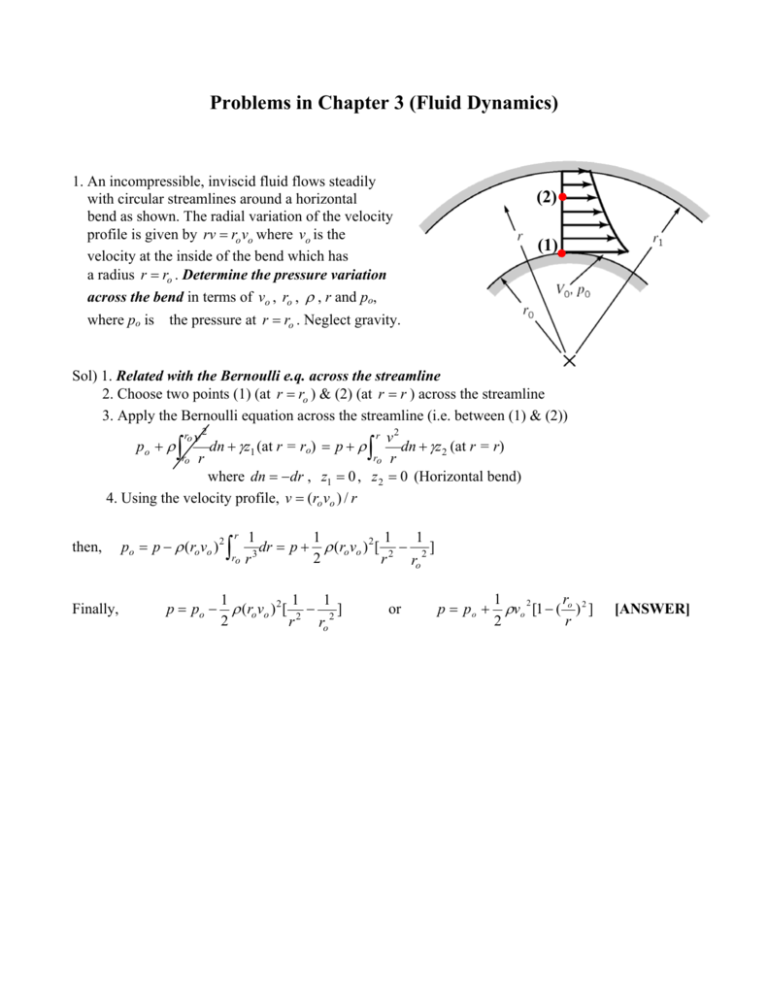
Problems in Chapter 3 (Fluid Dynamics) 1. An incompressible, inviscid fluid flows steadily with circular streamlines around a horizontal bend as shown. The radial variation of the velocity profile is given by rv = ro vo where vo is the velocity at the inside of the bend which has a radius r = ro . Determine the pressure variation across the bend in terms of vo , ro , ρ , r and po, where po is the pressure at r = ro . Neglect gravity. (2) (1) Sol) 1. Related with the Bernoulli e.q. across the streamline 2. Choose two points (1) (at r = ro ) & (2) (at r = r ) across the streamline 3. Apply the Bernoulli equation across the streamline (i.e. between (1) & (2)) ro v 2 r v2 po + ρ dn + γz1 (at r = ro) = p + ρ dn + γz2 (at r = r) ro r ro r where dn = −dr , z1 = 0 , z 2 = 0 (Horizontal bend) 4. Using the velocity profile, v = (ro vo ) / r ∫ then, Finally, ∫ po = p − ρ (ro vo ) 2 p = po − ∫ r ro 1 1 1 1 dr = p + ρ (ro vo ) 2 [ 2 − 2 ] 3 2 r r ro 1 1 1 ρ (ro vo ) 2 [ 2 − 2 ] 2 r ro or p = po + r 1 ρvo 2 [1 − ( o ) 2 ] r 2 [ANSWER] 2. Water flows from the faucet on the first floor of the building shown with a maximum velocity of 20 ft/s. For steady inviscid flow, determine the maximum water velocity from the basement faucet and from the faucet on the second floor (assume each floor is 12 ft tall). Sol) From the simplified diagram as shown, Bernoulli’s equation along the streamline; p1 + 1 1 ρv12 + γz1 = p2 + ρv2 2 + γz 2 [Between (1) and (2) (Basement)] 2 2 1 2 = p3 + ρv3 + γz3 [Between (1) and (3) (1st floor)] 2 1 = p4 + ρv4 2 + γz 4 [Between (1) and (4) (2nd floor)] 2 Since all pressures at the faucets (p2, p3, p4) are zero (Free jet) a) Water velocity at the basement faucet 1 1 p3 + ρv3 2 + γz3 = p2 + ρv2 2 + γz 2 2 2 (4) 16 ft (3) 4 ft (1) 8 ft (2) v2 = ∴ 2⎡ 1 ⎤ 2 2 p3 + ρv3 + γ ( z3 − z 2 ) − p2 ⎥ = v3 + 2 g ( z3 − z 2 ) ⎢ ρ⎣ 2 ⎦ (where v3 = 20 ft/s, and z3 − z2 = 12 ft) = (20) 2 + 2(32.2)(12) = 34.2 ft/s [since p2 = p3 = 0] [ANSWER] b) Water velocity at the faucet on the second floor 1 1 2 2 p3 + ρv3 + γz3 = p4 + ρv4 + γz 4 2 2 v4 = 2⎡ 1 ⎤ 2 2 p3 + ρv3 + γ ( z3 − z 4 ) − p4 ⎥ = v3 + 2 g ( z3 − z 4 ) ⎢ ρ⎣ 2 ⎦ (where v3 = 20 ft/s, and z3 − z4 = − 12 ft) [since p4 = p3 = 0] = (20) 2 + 2(32.2)(−12) = − 372.8 : Imaginary → Unreal physical value ∴ No water at the second floor [ANSWER] 3. (Bernoulli eq. & Continuity) Water flows into a large tank at a rate of 0.011 m3/s as shown. The water leaves the tank through 20 holes in the bottom of the tank, each of which produces a stream of 10-mm diameter. Determine the equilibrium height, h, for steady state operation. (1) Sol) 1. The equilibrium height h - Related with the continuity eq. Q1 (into a tank) = Q2 (leaving through holes) or 0.011 = 20 (holes) A2V2 = 20 π 4 (2) 2 D2 v2 2. In order to determine v2, the Bernoulli eq. along a streamline p1 + 0+ 1 2 1 ρv1 + γz1 = p2 + ρv2 2 + γz2 2 2 where p1 = p2 = 0 (atmosphere), z1 = h , z 2 = 0 , v1 = 0 1 1 ρ (0) 2 + γ (h) = 0 + ρv2 2 + γ (0) 2 2 & v 2 = 2 gh 3. Insert v2, determined from the Bernoulli eq. into the continuity eq. 4. (Bernoulli eq. & Continuity) Water flows through a pipe reducer as shown. The static pressures at (1) and (2) are measured by the inverted U-tube manometer containing oil of specific gravity, SG, less than one. Determine the manometer reading, h. (B) (C) (A) Sol) l 1. U-tube manometer reading From (1) → (A) → (B) → (C) → (2) p1 − γ ( z 2 − z1 ) − γl − γh + γ oil h + γl = p2 where γ oil = SGγ or p1 − p2 = γ ( z 2 − z1 ) + (1 − SG )γh 2. p1 − p2 : To be determined from the Bernoulli eq. 1 2 1 2 p1 + ρv1 + γz1 = p2 + ρv2 + γz2 2 2 1 1 or p1 − p2 = γ ( z 2 − z1 ) + ρv2 2 − ρv12 2 2 3. By comparing two eqs., ⎡ ⎛ v ⎞2 ⎤ 1 1 2 2 2 (1 − SG )γh = ρ [v2 − v1 ] = ρv2 ⎢1 − ⎜⎜ 1 ⎟⎟ ⎥ 2 2 ⎢⎣ ⎝ v2 ⎠ ⎥⎦ 4. v2 2 − v12 : To be determined from the continuity eq. (Confined flow) Q1 = A1v1 = π 4 D12 v1 = π 4 D2 v2 = A2 v2 = Q2 2 → 2 v1 A2 D2 = = v2 A1 D12 5. We need one more condition to determine v2, (e.g. Q = A2 v2 ) 5. (Bernoulli eq. & Continuity & Pitot tube) Two Pitot tubes and two static pressure taps are placed in the pipe contraction shown. The flowing fluid is water, and viscous effects are negligible. Determine the two manometer readings, h and H. (C) (D) l3 (4) (3) (1) l1 (2) (B) Sol) (1) Manometer reading h between (1) & (2) (A) From (1) → (A) → (B) → (2) p1 + γl1 − SGγh − γ (l1 − h) = p2 or where γ oil = SGγ (1 − SG )γh = p2 − p1 (Ú Independent to l1) y p2 − p1 : To be determined from the Bernoulli eq. 1 1 2 2 p1 + ρv1 + γz1 = p2 + ρv2 + γz 2 2 2 where, z1 = 0 , z 2 = 0 , v1 = 0 & v2 = 0 (Stagnation points!!) ∴ p 2 − p1 = 0 and thus h=0 (2) Manometer reading H between (3) & (4) [ (3) → (C) → (D) → (4)] p3 − γ (l3 − or γ (H − 1 ) + γ Air H + γ (l3 − H ) = p4 12 where γ Air : Negligible 1 ) = p3 − p4 12 y p3 − p4 : To be determined from the Bernoulli eq. & the continuity eq. p3 + 1 1 ρv32 + γz3 = p4 + ρv4 2 + γz4 2 2 where, z3 = 3 / 12 ft, z 4 = 2 / 12 ft, v3 = 2 ft/s, v4 = A3 v3 A2
