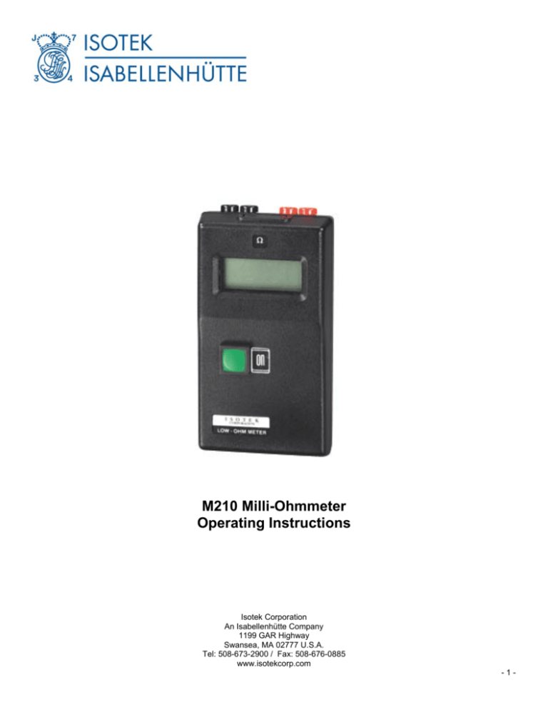
M210 Milli-Ohmmeter Operating Instructions
advertisement

M210 Milli-Ohmmeter Operating Instructions Isotek Corporation An Isabellenhütte Company 1199 GAR Highway Swansea, MA 02777 U.S.A. Tel: 508-673-2900 / Fax: 508-676-0885 www.isotekcorp.com -1- Toll Free: 800-LOW-OHMS Unique Benefits of the M210 Milli-Ohmeter · Truly Portable · 1 milliohm to 200 Ohms · 0.1% accuracy · Safe test current - 5 mA max. This battery-operated digital resistance meter is designed to measure accurately low resistances from 0.001 Ohm to 200 Ohms, using four-terminal measurement network which eliminates errors caused by test lead resistance. The instrument is small and lightweight and is used easily in one hand with only an ON button to operate. It has auto-ranging, autodecimal point and auto-powerdown after three minutes. It has long battery life and is powered by a single 9V battery. Typical Applications · Relay, switch and connector contacts · Weld Integrity · PC-plated through holes and track resistance · Transformer and motor windings · Ring circuit testing · Earth conductor continuity · RFI shielding and coil resistance Specifications Ranges (selected automatically) Increment Accuracy Zero offset Test current Test power Temperature drift Operating range Display Weight : Approximate dimensions Instrument : Approximate dimensions Case : Battery: Supplied Accessories: 1.999, 19.9, 199.9 Ohms 0.001, 0.01, 0.1 Ohms ± 0.1% of range ± 0.001 Ohms 5 mA maximum 5 mW maximum 0.1% °C of lowest range 5 to 35 °C 3-1/2 L.C.D. 1 lb. 3 oz. 5.7” H x 3.25” W X 1.43” D 6.1” H x 5.65” W x 1.8” D 9v Carrying case w/ strap, M210/9A Kelvin clip leads Isotek Corporation An Isabellenhütte Company 1199 GAR Highway Swansea, MA 02777 U.S.A. Tel: 508-673-2900 / Fax: 508-676-0885 www.isotekcorp.com 2 Toll Free: 800-LOW-OHMS The measuring circuit In the four-terminal "Kelvin" configuration four wires are used to connect the circuit under test to the instrument. One pair of wires carries current generated by the instrument; the other pair connects to the voltage-measuring circuit. The current circuit is low impedance, the voltage circuit high impedance. When connected a current flows through the component or circuit under test and the voltage drop across the test points is measured. Schematic Circuit 4-Terminal Method of Resistance measurement The ratio between the current and the voltage drop is calculated by the instrument using Ohm's law (R = E/I) to display the result in Ohms. Four clips would normally be required for connection but this can be tedious, therefore a special form of clip is used with the M210. The jaws are molded in durable plastic and inset into each jaw face is a copper/silver inlay contact; these are insulated from each other by the plastic moldings. One contact face on each clip is connected to the current-generating circuit; the other face is connected to the voltage-measuring circuit. In this way four wires are connected instantly by two clips. The resistance of the connecting wires is eliminated from the measurement. Instructions for use Using standard clip leads M210/9A (supplied as standard) 1. Plug either black plug into either black socket in the top of the instrument and red plugs into red sockets. 2. Clip leads to circuit or component to be tested. Ensure that both faces of clip make good electrical contact. 3. Press the ON button to read resistance. Isotek Corporation An Isabellenhütte Company 1199 GAR Highway Swansea, MA 02777 U.S.A. Tel: 508-673-2900 / Fax: 508-676-0885 www.isotekcorp.com 3 Toll Free: 800-LOW-OHMS Using Probe and Contact Connectors M210/9B (optional extra) 1. Insert plugs into their respective sockets as illustrated. The outer plugs form the current circuit via the clips. The inner plugs (with yellow bands) connect the probes in the voltage measuring circuit. 2. Clip leads to circuit under test. 3. Press ON button to read resistance when the probes are in contact with the circuit. Interpreting the Display 1. The M210 will read directly in ohms or milli-ohms. 2. FLUCTUATING READINGS DISPLAYED. Check that the clips are making good contact with the circuit under test, then look for the cause of intermittency, e.g. dry solder joint, oxidized or corroded terminals; slight mechanical movement of the component(s) in the circuit under test. This should quickly reveal the source of the problem. 3. FLASHING "1" indicates that resistance in circuit exceeds 200 Ohms. 4. "LO BAT" displayed indicates low battery. Battery Replacement Slide down the cover at the rear, bottom of the instrument. Fit new 9 volt battery. Replace cover. Test Procedures Using standard lead set for checking 1. Checking continuity value and mechanical stability of resistive components. Also used to measure resistance/temperature coefficient: R2 - R1------------- x 100R1 (t2 - t1) 2. Testing the resistance of windings to determine continuity, good electrical connection to tails and to ascertain resistive imbalance in center-tapped transformers. Isotek Corporation An Isabellenhütte Company 1199 GAR Highway Swansea, MA 02777 U.S.A. Tel: 508-673-2900 / Fax: 508-676-0885 www.isotekcorp.com 4 Toll Free: 800-LOW-OHMS 3. Checking the electro-mechanical stability of printed circuits and mounted components. Dry solder joints can be located by connecting one clip to the track, the other clip to the component tail or tag. 4. Ensuring that earth points make good electrical contact to ground strip or chassis. Looking for defects due to rust, corrosion or defective plating and anodic films. 5. Plugs and sockets of all types rely on friction contact between mating surfaces. Looking for defects due to oxidization, grease or dirt. 6. Testing ring mains circuits to meet Appx. 15 IEE wiring regulations. The resistance in the ring, including the resistance of the protective conductor, are checked before and after connection. Using probe and lead clips 7. Multi-tapped transformers are quickly checked and the tapping points identified on an unknown transformer or coil assembly. Isotek Corporation An Isabellenhütte Company 1199 GAR Highway Swansea, MA 02777 U.S.A. Tel: 508-673-2900 / Fax: 508-676-0885 www.isotekcorp.com 5 Toll Free: 800-LOW-OHMS 8. Etching defects show up as an unexpected variation in track resistance. 9. Through hole plated tracks on a PCB are checked for continuity and unexpectedly high resistance. 10. Clipping the leads to the probes makes for an easy-to-use continuity tester which is accurate. 11. Welded joints, which are imperfect, have a high resistance. Aluminum welds over 0.7 Ohms are rejected. Small variations in resistance might indicate inclusions or voids in the weld. Isotek Corporation An Isabellenhütte Company 1199 GAR Highway Swansea, MA 02777 U.S.A. Tel: 508-673-2900 / Fax: 508-676-0885 www.isotekcorp.com 6


