Internal Combustion Engines Engine Classification Advantages and
advertisement
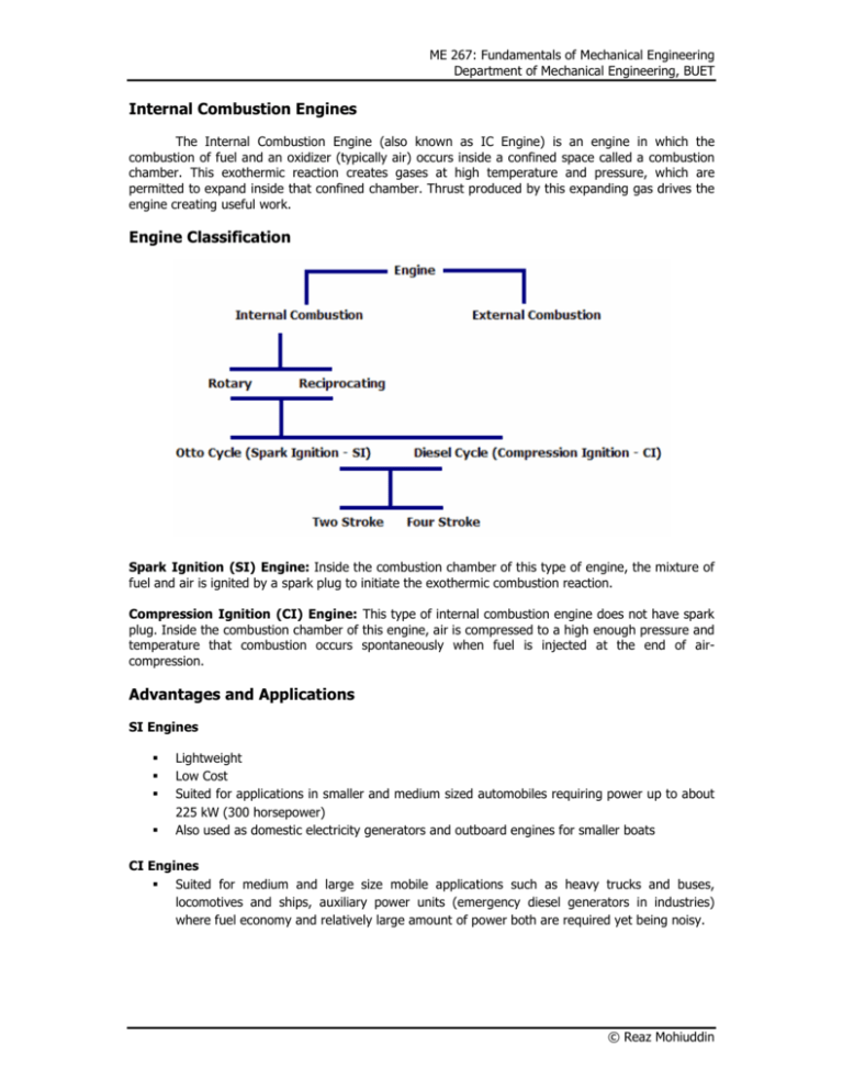
ME 267: Fundamentals of Mechanical Engineering Department of Mechanical Engineering, BUET Internal Combustion Engines The Internal Combustion Engine (also known as IC Engine) is an engine in which the combustion of fuel and an oxidizer (typically air) occurs inside a confined space called a combustion chamber. This exothermic reaction creates gases at high temperature and pressure, which are permitted to expand inside that confined chamber. Thrust produced by this expanding gas drives the engine creating useful work. Engine Classification Spark Ignition (SI) Engine: Inside the combustion chamber of this type of engine, the mixture of fuel and air is ignited by a spark plug to initiate the exothermic combustion reaction. Compression Ignition (CI) Engine: This type of internal combustion engine does not have spark plug. Inside the combustion chamber of this engine, air is compressed to a high enough pressure and temperature that combustion occurs spontaneously when fuel is injected at the end of aircompression. Advantages and Applications SI Engines Lightweight Low Cost Suited for applications in smaller and medium sized automobiles requiring power up to about 225 kW (300 horsepower) Also used as domestic electricity generators and outboard engines for smaller boats CI Engines Suited for medium and large size mobile applications such as heavy trucks and buses, locomotives and ships, auxiliary power units (emergency diesel generators in industries) where fuel economy and relatively large amount of power both are required yet being noisy. © Reaz Mohiuddin ME 267: Fundamentals of Mechanical Engineering Department of Mechanical Engineering, BUET Engine Terminology Piston Cylinder Assembly: It is the assembly for manipulating the working fluid. The assembly is characterized by a piston moving inside the confined cylinder. Inlet Valve: The valve through which air fuel mixture (in case of SI engine) or air (in case of CI engine) is introduced inside the cylinder. Exhaust Valve: The valve through which the products of combustion leave the cylinder. Crank Mechanism: Mechanism to convert reciprocating piston motion to rotary motion. Bore: Diameter of Cylinder. Top Dead Center (TDC): Position of Piston where Cylinder Volume is minimum. Bottom Dead Center (BDC): Position of Piston where Cylinder Volume is maximum. Stroke: It is the maximum distance that the piston moves in one direction. It is the distance between TDC to BDC. Clearance Volume (Vc): Minimum Cylinder volume when Piston is at TDC. Displacement Volume (Vd): Volume swept out by the Piston as it moves from TDC to BDC. Compression Ratio (rv): Ratio of volume at TDC and volume at BDC. rv = Vd Vc + V d © Reaz Mohiuddin ME 267: Fundamentals of Mechanical Engineering Department of Mechanical Engineering, BUET Actual 4-stroke Engine P-V Diagram Fig.: Actual PV diagram for an internal combustion engine In an internal combustion engine, the piston executes four distinct strokes within the cylinder for every two revolutions of the crankshaft. The four strokes are termed as – Intake Stroke Compression Stroke Power Stroke Exhaust Stroke Intake Stroke Intake valve opens. Piston moves from TDC to BDC. Fresh charge is drawn into the cylinder due to suction. For SI engine the charge is a mixture of fuel and air. For CI engines charge is only air. Compression Stroke Intake and Exhaust both valves remain closed. Piston rises from BDC to TDC and compresses the charge, raising the temperature and pressure. This stroke requires work input from Piston to the charge. Combustion is induced near the end of the compression stroke. In SI engines it is induced by spark plug. In CI engines combustion is initiated by injecting fuel into the hot-compressed air using fuel injectors. © Reaz Mohiuddin ME 267: Fundamentals of Mechanical Engineering Department of Mechanical Engineering, BUET Power Stroke Power Stroke follows the compression stroke during which the gas mixture expands due to exothermic blast of fuel and air mixture. Work in done on the Piston as thermal energy is converted to mechanical energy. Piston moves from TDC to BDC. Exhaust Stroke Piston moves from BDC to TDC due to momentum gained. Exhaust Valve opens Burned gases are purged from the cylinder through the exhaust valve. Inlet conditions in actual engines Inlet Pressure < Exhaust Pressure: Inlet Pressure = Exhaust Pressure: Inlet Pressure > Exhaust Pressure: Throttled Engine Unthrottled Engine/Naturally Aspirated Engine Supercharged (inlet air is compressor driven by engine) Turbocharged (inlet air is compressor driven by exhaust GT) Complexities in detailed study of Actual Cycle Incorporation of Friction Losses, Pressure and Temperature Gradients. Heat Transfer calculations between gases and the cylinder walls. Calculation of work required to charge the cylinder and purge the cylinder. Change in composition of the gaseous contents inside the Cylinder during Combustion. Assumptions made for Elementary Thermodynamic Analysis of IC Engines Air-Standard Cycle Assumptions: Working fluid is fixed amount of air modeled as ideal gas. No change in composition. Combustion process is replaced by Heat Transfer from an External Source. There is no Intake and Exhaust Strokes like an actual engine. All the processes are internally reversible i.e. there is no friction or heat loss. Specific heats are assumed constant at their ambient temperature values. (Cold Air-Standard) Although an air-standard analysis simplifies the study of internal combustion engines considerably, the values of different parameters (pressure, temperature) calculated on this basis may depart significantly from those of actual engines. Air-Standard analysis allows internal combustion engines to be examined only qualitatively. Thermodynamic cycles that adhere to air-standard assumptions are – Otto Cycle of Petrol Cycle (for SI Engines) Diesel Cycle (for CI Engines) © Reaz Mohiuddin ME 267: Fundamentals of Mechanical Engineering Department of Mechanical Engineering, BUET Air Standard Otto or Petrol Cycle Fig.: P-V and T-s diagram for air standard Otto cycle The air-standard Otto cycle assumes the heat addition to be occurring instantaneously while the piston is at TDC. Therefore in petrol cycle, heat addition will take place at constant volume. This is due to the fact that the pressure inside the cylinder will rise rapidly during the combustion period as soon as ignition of air-fuel mixture is started by a spark plug. There are four processes occurring in series and all of them are internally reversible. Process 1-2: Isentropic Compression. Piston: BDC TDC Process 2-3: Constant Volume Heat Addition. Piston: at TDC Process 3-4: Isentropic Expansion (Power Stroke). Piston: TDC BDC Process 4-1: Constant Volume Heat Rejection. Piston: at BDC The areas in the P-V diagram indicate work input and output into and from the cycle as we have taken all the process to be internally reversible i.e. neglected all the losses. The expression for work is W = ∫ P dV. In the P-V diagram: Area 1-2-a-b-1: Work input per unit mass during the compression process. Area 3-4-b-a-3: Work done per unit mass in the expansion process. Area 3-4-1-2: Net Work Output. Similarly, the areas in the T-s diagram can be interpreted due to the thermodynamic relation between heat (Q), temperature (T) and entropy (s) and Q = ∫T ds. In the T-s diagram: Area 2-3-a-b-2: Quantity of Heat added to unit mass of air from any External Source. Area 1-4-a-b-1: Quantity of Heat rejected to unit mass of air from any External Source. Area 1-2-3-4: Quantity of Net heat added to unit mass of air from any External Source. © Reaz Mohiuddin ME 267: Fundamentals of Mechanical Engineering Department of Mechanical Engineering, BUET Cycle Analysis: Process 1-2: Isentropic Compression Process 2-3: Constant Volume Heat Addition Process 3-4: Isentropic Expansion: Same expression as Process 1-2 but here the points will be 3 and 4. Process 4-1: Constant Volume Heat Rejection Compression Ratio (rv): Thermal Efficiency (ηth): From the isentropic process relations and the expression of compression ratio it can be proven that – Effect of Compression Ratio on Performance: The above thermodynamic analysis indicates that the cold air-standard Otto cycle thermal efficiency is a function of compression ratio (r) and specific heat ratio (k=Cp/Cv). For k=1.4 this relationship is shown below- Fig.: Effect of compression ratio on thermal efficiency of a SI engine The foregoing discussion suggests that it is advantageous for SI engines to have higher compression ratios. But the possibility of autoignition or knock, places an upper limit on the compression ratio of SI engine. After the spark has ignited a portion of the fuel-air mixture, the rise on pressure © Reaz Mohiuddin ME 267: Fundamentals of Mechanical Engineering Department of Mechanical Engineering, BUET accompanying combustion compresses the remaining charge. Autoignition can occur if the temperature of the unburned mixture becomes too high before the mixture is consumed by the flame front. Since the temperature attained by the air-fuel mixture during the compression stroke increases as the compression ratio increases, the likelihood of autoignition occurring increases with the compression ratio. Knocking in SI Engines: Knocking in SI Engines refers to the pinging noise and vibration as a result of high pressure waves colliding with one another due to Autoignition of fuel-air mixture (inside the cylinder). Continuation of this phenomenon may lead to engine damage or loss of engine output power. Prevention of Knocking and optimum value of compression ratio: Fuels formulated with tetraethyl lead (TEL) are resistant to autoignition. But unleaded gasoline is used these days due to environmental concerns over air pollution that limits the compression ratios of spark-ignition engines to approximately 9. © Reaz Mohiuddin ME 267: Fundamentals of Mechanical Engineering Department of Mechanical Engineering, BUET Air Standard Diesel Cycle Fig.: P-V and T-s diagram for air standard Diesel cycle Air standard Diesel Cycle assumes the heat addition occurs during a constant pressure process that starts with the piston at TDC. This is based on the fact that as the fuel-air mixture starts to burn after fuel is injected into the cylinder containing hot, compressed air, the pressure rises; but as the piston also moves down, the rise in pressure is counterbalanced by increase in cylinder volume. Therefore, the pressure remains constant for initial period of power stroke. As the amount of unburned charge diminishes gradually in the later part of the power stroke, the pressure rise cannot keep pace with the volume increase. As a result of that the pressure falls in later part of the power stoke. The period upto which the pressure remains constant is called the pressure Cut-off region. There are four processes occurring in series and all of them are internally reversible. Process 1-2: Isentropic Compression. Piston: BDC TDC Process 2-3: Constant Pressure Heat Addition (1st part of Power Stroke). Piston: TDCBDC Process 3-4: Isentropic Expansion (Remainder of Power Stroke). Piston: TDCBDC Process 4-1: Constant Volume Heat Rejection. Piston: at BDC The Areas in the p-v diagram indicate work input and output into and from the cycle as we have taken all the process to be internally reversible i.e. neglected all the losses. The expression for work is W = ∫ P dV. In the P-V diagram: Area 1-2-a-b-1: Work input per unit mass during the compression process. Area 2-3-4-b-a-2: Work done per unit mass in the expansion process. Area 3-4-1-2: Net Work Output. Similarly, the areas in the T-s diagram can be interpreted due to the thermodynamic relation between heat (Q), temperature (T) and entropy (s) and Q = ∫T ds. © Reaz Mohiuddin ME 267: Fundamentals of Mechanical Engineering Department of Mechanical Engineering, BUET In the T-s diagram: Area 2-3-a-b-2: Quantity of Heat added to unit mass of air from any External Source. Area 1-4-a-b-1: Quantity of Heat rejected to unit mass of air from any External Source. Area 1-2-3-4: Quantity of Net heat added to unit mass of air from any External Source. Cycle Analysis: In air standard Diesel cycle the processes 1-2, 3-4 and 4-1 are same as air-standard Otto cycle. The difference is in the process 2-3 where the heat transfer is thought to be at constant pressure. Therefore the expression for the process 2-3 is given below – The heat transfer process being a constant pressure one then the relation between volume and temperature in this process is as follows – Cut-off Ratio (rc): rc = V3 V2 Compression Ratio (rv): rv = V1 V2 Therefore, it can be proven from the above relations that: 1 rck − 1 η th = 1 − k −1 rv k ( rc − 1) Effect of Compression Ratio (rv) on Performance: On a cold air-standard basis, the thermal efficiency of the Diesel Cycle can be expressed as the above equation. The equation of thermal efficiency for the Diesel Cycle differs from that of Petrol Cycle only by the term in the brackets, which for rc > 1 is greater than unity. Thus, when the compression ratio is same, thermal efficiency of the cold air-standard Diesel Cycle would be less than that of the cold air-standard Petrol Cycle. Fig.: Effect of compression ratio on thermal efficiency of a CI engine © Reaz Mohiuddin ME 267: Fundamentals of Mechanical Engineering Department of Mechanical Engineering, BUET Compression Ratio of a Diesel Engine in comparison with Otto Cycle Higher compression ratios can be achieved in compression-ignition engines because air alone is compressed. Compression ratios in the range of 12 to 20 are typical. Compression-ignition engines also can use less refined fuels having higher ignition temperatures than the volatile fuels required by the spark-ignition engines. Engine Performance Parameters Mean Effective Pressure The mean effective pressure (MEP) is the theoretical constant pressure that, if acted on the piston during the power stroke, would produce the same net work as actually developed in one cycle. MEP×displacement volume = ∫ P dV MEP = (∫ P dV) / displacement volume Physical Significance of MEP: For two engines of equal displacement volume, the one with a higher mean effective pressure would produce the greater net work and if the engines run at the same speed, would produce greater power of the two. Class Problem 01 The Compression Ratio in an air-standard Otto Cycle is 8. At the beginning of the compression stroke the pressure in 0.1 MPa and the temperature is 15°C. The heat transfer to the air per cycle is 1800 kJ/kg air. Determine: (a) The pressure and temperature at the end of each process of the cycle. (b) The thermal efficiency. (c) The mean effective pressure. Class Problem 02 Find out the parameters in the above stated problem for a Diesel Engine having a Compression Ratio of 16. Compare your result. © Reaz Mohiuddin

