Protection Relays MiCOM P111Enh
1
MiCOM P111Enh
Numerical three phase and earth fault overcurrent relays
The MiCOM P111Enh (Enhancement) relays are suitable for all the
application where overcurrent and/or earth-fault protection are required.
P111Enh can be applied to medium and low voltage electrical systems
as an optimized and cost efficient solution tailored to user’s needs.
MiCOM P111Enh relays provide features for easy adaptation to different
applications and operation conditions.
The P111Enh can be fully configured manually, without using setting
software.
Alternatively, MiCOM S1 Studio setting software allows configuration
parameters to be modified for a specific application via the USB port.
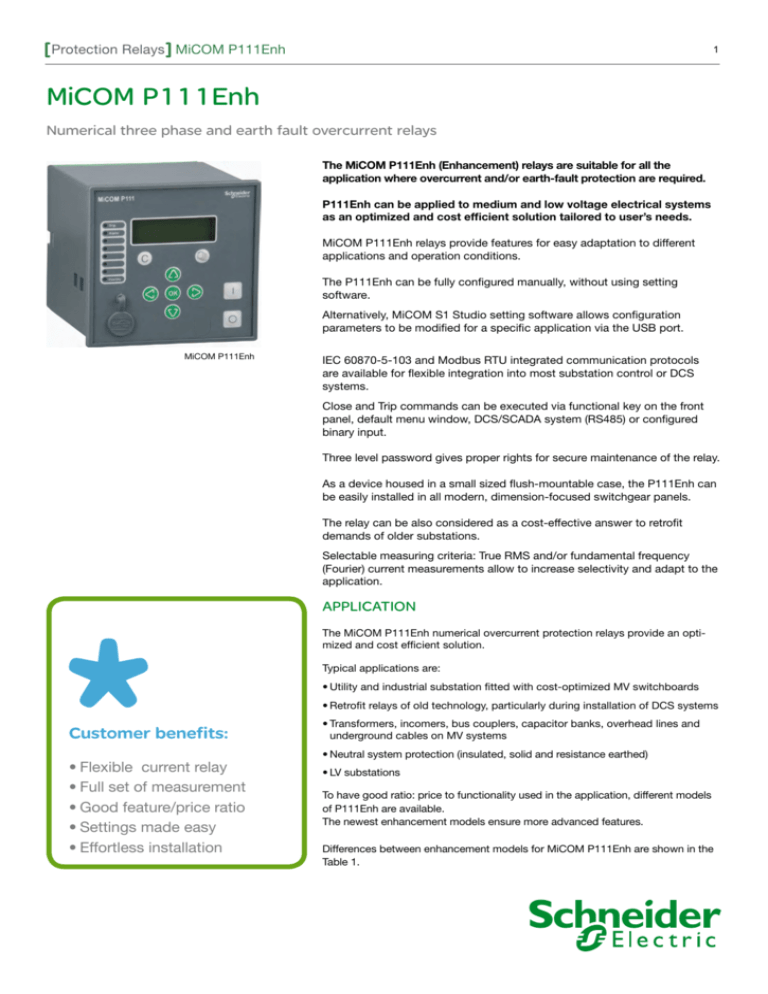
MiCOM P111Enh
IEC 60870-5-103 and Modbus RTU integrated communication protocols
are available for flexible integration into most substation control or DCS
systems.
Close and Trip commands can be executed via functional key on the front
panel, default menu window, DCS/SCADA system (RS485) or configured
binary input.
Three level password gives proper rights for secure maintenance of the relay.
As a device housed in a small sized flush-mountable case, the P111Enh can
be easily installed in all modern, dimension-focused switchgear panels.
The relay can be also considered as a cost-effective answer to retrofit
demands of older substations.
Selectable measuring criteria: True RMS and/or fundamental frequency
(Fourier) current measurements allow to increase selectivity and adapt to the
application.
APPLICATION
The MiCOM P111Enh numerical overcurrent protection relays provide an optimized and cost efficient solution.
Typical applications are:
•Utility and industrial substation fitted with cost-optimized MV switchboards
•Retrofit relays of old technology, particularly during installation of DCS systems
Customer benefits:
•Flexible current relay
•Full set of measurement
•Good feature/price ratio
•Settings made easy
•Effortless installation
•Transformers, incomers, bus couplers, capacitor banks, overhead lines and
underground cables on MV systems
•Neutral system protection (insulated, solid and resistance earthed)
•LV substations
To have good ratio: price to functionality used in the application, different models
of P111Enh are available.
The newest enhancement models ensure more advanced features.
Differences between enhancement models for MiCOM P111Enh are shown in the
Table 1.
Protection Relays MiCOM P111Enh
MAIN FEATURES
The following functions are generally available in all devices (refer to Table 1
below):
• Operate in 1, 2, or 3-phase arrangement.
• Two setting groups, selected from the relay menu, binary input or SCADA/DCS.
• Flush mounted case.
• Fundamental (fn) and True RMS (within a frequency range from 40Hz to
1kHz) phase current value measurement.
• Earth current fundamental (fn) frequency measurement.
• 9 button keypad to input settings, configure the relay and close and trip
command and display (2x16 LCD).
50N/51N
The P111Enh protection relays are comprised
of full suite of protection functions as well as
automatic recloser and auxiliaries. Each function
can be individually configured or disabled to suit
every kind of application.
All available functions, including protection,
automation, communication, LEDs, inputs and
outputs, are easily programmable through the
user-friendly human machine interface and/or the
MiCOM S1 STUDIO software interface.
L
N
Models
B
Three-phase non directional overcurrent: 3 independent
thresholds (12 groups of IDMT curves)
•
•
•
•
•
Phase-earth non directional overcurrent. Independent thresholds (12 groups of IDMT curves):
2
2
2
2
3
•
•
•
•
ANSI Code Functions
50/51
2
A
E
49
Thermal overload (true RMS): 2 independent thresholds (Alarm,
Trip)
46
Negative phase sequence overcurrent
•
46BC
Broken conductor detection (I2/I1)
•
50/51
Switch on to fault (SOTF)
•
•
•
•
•
•
•
•
•
•
Inrush blocking
Blocking logic
Selective relay scheme logic
Cold Load Pick-Up
79
50BF
•
•
•
•
•
•
•
2 setting groups
•
•
•
•
•
Self-monitoring feature with watchdog contact WD
1
1
1
1
1
0/3+WD
0/5+WD
4/3+WD
4/7+WD
8/5+WD
Output relay latching
•
•
•
•
•
8 signalling LEDs (“Healthy” + “Trip” + “Alarm” + 5 freely configurable LEDs)
•
•
•
•
•
•
•
Freely configurable binary inputs / output relays
86
•
•
Autorecloser option (4 shots)
Circuit breaker failure
•
Circuit breaker supervision and counters
Trip circuit supervision
•
•
•
•
•
•
•
option
•
•
•
•
•
•
•
relay
powering
relay
powering
relay
powering
option
•
•
•
•
LCD display
•
•
back-lit
back-lit
back-lit
Measurements
•
•
•
•
•
•
•
•
Fault records for the 20 most recent trips
Event records (up to 200 events)
Disturbance records (up to 4 s)
Front USB port for local downloading of settings,
events and/or fault records
Rear port RS485 communications (Modbus RTU and
IEC60870-5-103)
Binary input for time synchronization via external clock
•
CB control: HMI, via binary input or RS485
Setting software: MiCOM S1 and/or S1 Studio
Optional cassette (adaptor) for: wall-mounted solution
Table 1. Functions of P111 Enhancement Models
•
option
•
•
•
•
•
•
•
•
•
Protection Relays MiCOM P111Enh
3
Technical Characteristics
Weight
MiCOM P111Enh N type
0.5 kg
Phase current inputs
Nominal current (In)
1A or 5A (selectable via setting)
Nominal earth fault input current (Ien)
1A or 5A (selectable via setting)
RMS measurement range (In)
40Hz ~ 1KHz
Fundamental harmonic measurement range (In,Ien)
40Hz ~ 70Hz
Operating range
In
0.1 ~ 40In
Ien
0.05 ~ 12Ien
<0.3VA at In,Ien=5A ; <0.1VA at In,Ien=1A
Nominal burden
Thermal withstand
continuous
4In , Ien
10s
30In , Ien
2s
40In , Ien
1s
100In , Ien
Digital output contacts
6DO, Ag-Ni alloy
6 dry contacts
Contact capacity
continuous
5A, 250Vac/Vdc
short time
30A for 1s / 25A for 3s
making
150A for 30ms
AC breaking
1250VA resistive (cosø=unity)
1250VA inductive (cosø=0.7)
DC breaking
50W resistive
25W inductive (L/R=40ms)
<10ms
Operating time
Endurance
electrical
10,000 operations minimum
mechanical
100,000 operations minimum
Power supply
Voltage
24 ~ 240Vac / 24 ~ 250Vdc
Frequency
50/60Hz
Insulation
Insulation resistance
EN 60255-5: 2001
>500MΩ at 500Vdc
Dielectric withstand
EN 60255-27: 2005
2kV rms AC, 1 minute
Impulse voltage withstand
EN 60255-27: 2005
1.2/50μs, 5kV
Creepage distance & clearance
EN 60255-27: 2005
pollution degree 2
overvoltage category III
EMC tests
EN 55022, EN 61000, EN 60255
Environmental characteristics
Ambiant temperature
operation
-25oC ~ +60oC
storage
-25oC ~ +70oC
56 days at 93% RH, +40oC
Humidity
Protection class
housing
IP40
terminal
IP20
front panel
IP54
Protection Relays MiCOM P111Enh
4
Protection Setting Ragnes
Functions
Settings
Time delays
ANSI 50/51 - Phase overcurrent
Tripping curve
Current threshold I>
Definite time
DT
IEC: SIT/A, VIT/B, EIT/C, LTI
IDMT
0.1 to 40In
Timer hold tI>
Current threshold I>>
Inst ; 0.05 to 200s
IDMT
TMS ; 0.02 to 200s
DT
Inst ; 0.05 to 200s
IDMT
TMS ; 0.02 to 200s
DT
Inst ; 0 to 200s
0.1 to 40In
Timer hold tI>>
Current threshold I>>>
DT
1 to 40In
Timer hold tI>>>
ANSI 50N/51N - Earth fault
Tripping curve
Current threshold IN>
Definite time
DT
IEC: SIT/A, VIT/B, EIT/C, LTI
IDMT
0.05 to 12Ien
Timer hold tIN>
Current threshold IN>>
DT
Inst ; 0.05 to 200s
IDMT
TMS ; 0.02 to 200s
DT
Inst ; 0 to 200s
0.05 to 12Ien
Timer hold tIN>>
CLPU 50/51 - Phase overcurrent cold load pick-up
Cold load PU level
tCL ; 0 to 6000s
20 to 999%
ANSI 49RMS - Thermal overload
Time constant
1 to 200mn
heating
1 to 999mn
cooling
Thermal base current
0.1 to 3In
Alarm & tripping set points
alarm
20 to 200% of rated thermal capacity
trip
50 to 200% of rated thermal capacity
0.1 to 2In
overcurrent based
0.1 to 2Ien
earth fault current based
ANSI 50BF - Breaker failure
Presence current
Operating time
0.1 to 10s
Dimensions (mm)
5
101.5
101.5
113
106.5
106.5
15
Panel Cut
Protection Relays MiCOM P111Enh
5
Operation Time-Delay
The first (I>) and second (I>>) stages of overcurrent protection have time-delayed characteristics which are selectable
between inverse definite minimum time (IDMT) and definite time (DMT). The third (I>>>) stage has a definite time characteristic only.
Various methods are available to achieve correct relay co-ordination on a system; by means of time alone, current alone
or a combination of both time and current. Grading by means of current is only possible where there is an appreciable
difference in fault level between the two relay locations. Grading by time is used by some utilities but can often lead to
excessive fault clearance times at or near source substations where the fault level is highest.
For these reasons the most commonly applied characteristic in coordinating overcurrent relays is the IDMT type.
The inverse time-delayed characteristics indicated above comply with the following formulae:
IEC curves:
t=(
k
I
( )α − 1
Is
) • TMS
where:
t
=
Operating time in [s]
k
=
Constant
I
=
Measured current in [A]
TMS =
Time multiplier setting for IEC curves
Is
=
Current threshold setting [A]
α
=
Constant
Type of Curve
according to IEC 60255-151
standard definition
Standard
k
α
IEC Standard Inverse Time (SI)
IEC/A
0.14
0.02
IEC Very Inverse Time (VI)
IEC/B
13.5
1
IEC Extremely Inverse Time (EI)
IEC/C
80
2
IEC
120
1
IEC Long Time Inverse (LTI)
Standard Inverse IEC
Extremely Inverse IEC
Very Inverse IEC
100
100
100
10
10
B
A
1
B
Time [s]
A
Time [s]
Time [s]
10
1
A
C
C
1
B
D
0.1
0.1
D
C
E
E
0.1
0 1 2 3 4 5 6 7 8 9 10 11 12 13 14 15 16 17 18 19 20
Multiples of pickup setting: I/Is
E: TMS=0.05
B: TMS=1
D: TMS=0.2
A: TMS=2
C: TMS=0.5
0.01
D
E
0.01
0 1 2 3 4 5 6 7 8 9 10 11 12 13 14 15 16 17 18 19 20
0 1 2 3 4 5 6 7 8 9 10 11 12 13 14 15 16 17 18 19 20
Multiples of pickup setting: I/Is
Multiples of pickup setting: I/Is
E: TMS=0.05
B: TMS=1
D: TMS=0.2
A: TMS=2
C: TMS=0.5
E: TMS=0.05
D: TMS=0.2
B: TMS=1
A: TMS=2
C: TMS=0.5
Protection Relays MiCOM P111Enh
6
Connection Diagram
P2
S2
P1
S1
B
S2
S1
S2
la
A
C
lc
lb
S1
Output
Contact
RL4
C1
Output
Contact
RL5
C3
A1
R L4
C2
A2
Auxiliary
Voltage
Vx:
24~240Vac
24~250Vdc
A3
R L5
C4
A4
WD/R
L0
RL0
C5
Watchdog
WD/RL0
A5
Ia
C6
A6
C7
A7
Ib
C8
RL
L1
1
A8
C9
A9
Ic
C10
A10
RL
L2
2
C11
Output
Contact
RL2
A11
IN
C12
A12
RL
L3
3
C13
Output
Contact
RL1
A13
C14
A14
C15
A15
Output
Contact
RL3
A16
A17
+
RS485
RS485
-
A18
RS485
A19
USB
P111Enh Model N
Figure : Model N, typical connection to 3 Phase CTs. For other models please contact us.
Protection Relays MiCOM P111Enh
Functional Overview
7
(Description of ANSI code nos. see Functions Overview)
The 32 alphanumerical LCD (Enh) provides the
user with key information (faults, measurements,
settings, etc). The menus have a pull-down
structure for easy use and quick access to any
data. User can switch HMI language directly
through the front panel.
8 LEDs indicate the correct operation of the
relay as well as other information regarding the
protection of the electrical system.
The hardware architecture and software
algorithms have been designed to operate on
very short failure detection times. Tripping occurs
typically within no more than 40 ms.
USB
port
Rear port
Setting
software S 1
RS485 port
SCADA
system
79
I
50/51
50N
51N
Recording features
I/O features
Fault recording
20
LEDs
8
Event recording
200
Binary i nputs:
8
Flexible D ist.
Reco rder
Contact
Outputs: 6
AUXILIARY FUNCTIONS
MEASUREMENTS
-S OFT (Switch on to fault)
-C B Local/ Remote
-R emote ctrl on output relays
-A uxiliary timers
-S elf Diagnostic
-I nput synchronisation
-T wo setting groups
-P hase current
-R esidual current
-T rip, start, alarm couters
-A utoreclose counters
86
49
46
46 BC
50 BF
MODEL E
(Description of ANSI code nos. see Functions Overview)
PROTECTION FUNCTIONS
Three-Phase Overcurrent (50/51) & Earth Fault Overcurrent (50N/51N)
Three independent stages are available both for phase and earth fault
protection. For the first and second (50/51 only) stages the user may
independently select a definite time delay (DMT) or an inverse time delay
(IDMT) with different types of curves (IEC, IEEE, RI, RECT, RXIDG, BNP EDF).
Each stage and related time-delay can be programmed to provide maximum
selectivity.
The IDMT stages have a selectable reset feature:
DMT (0 to 600 s) or an IDMT timer so as to
reduce clearance times when intermittent faults
occur.
The MiCOM P111Enh relays have separate
instantaneous and delayed indications for
each stage and output relays and LEDs can be
configured to indicate the faulted phase(s).
Each protection stage can be disabled,
configured to trip a circuit-breaker or to issue an
ALARM signal only.
P111Enh Excellence in Balance
Protection Relays MiCOM P111Enh
Inrush current in transformer applications can have an influence on the
selectivity of instantaneous trips; the short time-delay (DMT) can therefore
be set for this protection element in order to maintain selectivity and make it
possible to have a current threshold below any inrush current peak.
Tripping
Characteristics
I th
Time
Switch-on-to-Fault (based on 50/51)
The closing of a circuit breaker might inadvertently lead to a short-circuit
fault due to a maintenance ground clamp not yet removed. The P111Enh
relays incorporate a settable switch-on–to-fault protection function. It
provides an instantaneous trip over a settable time period after local or
remote manual closure.
8
I>
t>
I>>
I<
t>>
I>>>
t>>>
One independent DMT current stage is available for phase fault protection.
Thermal Overload (49)
The protection of transformers and cables must take into account their
particular thermal characteristics.
Current
MiCOM P111Enh relays include a thermal replica element based on the true
RMS value of the current, up to the 10th harmonic. Alarm and Trip overload
thresholds and time constant are fully programmable to match each
application requirement.
Circuit Breaker Failure (50BF)
The circuit breaker failure protection function
verifies the effective opening of the CB using a
dedicated undercurrent threshold.
Negative Sequence Overcurrent (46)
The MiCOM P111Enh relays include a programmable function specially
designed to detect unbalanced load or fault conditions.
The circuit breaker failure function can be
activated by the trip of an internal protection
function and/or an external command through the
relevant digital input. The circuit breaker failure
protection function can also be used to trip
upstream circuit breakers.
The negative sequence overcurrent (I2>) stage has the same setting ranges
as the phase overcurrent function.
Thus, a negative sequence overcurrent element can operate for both phaseto-phase and phase-to-earth faults.
The I2> stage can be independently selected as a definite time DMT) or
inverse time-delay (IDMT) with different types of curves (IEC, IEEE/ANSI, RI,
RECT).
Broken Conductor (46BC)
A typical unbalanced fault that can occur on the system is an open circuit
fault. This fault can arise from a broken conductor, a discrepancy in the
position of the poles of one switchgear or a blown fuse.
MiCOM P111Enh relays can measure the ratio of negative to positive
sequence current (I2/I1).
This fully programmable function offers more sensitivity and stability than
pure negative sequence measurement.
Autorecloser (79)
MiCOM P111Enh dual-powered relays
incorporate a 4-shot autorecloser. All
programmed protection functions may
independently start any of the shots and the user
can program which functions are allowed to trip
after any of the shots.
To prevent an excessive number of reclosing
cycles in a short period of time, a setting can be
used to define the maximum number of reclosing
cycles allowed in a period of time after the first
one was detected.
Dead and reclaim times are freely adjustable.
Front panel LEDs can be configured to display
the status of the autorecloser.
A counter stores the number of reclose
commands. This information can be displayed
either locally or remotely.
Inrush Blocking
The 2nd Harmonic Blocking detects high inrush
current inflows that occur upon connection of
transformers or rotating machines. The function
will block the phase overcurrent, earth fault and
negative sequence overcurrent elements (freely
selectable).
Protection Relays MiCOM P111Enh
Timers AUX1, AUX2, AUX3, AUX4
Timers operate if the state of an input mapped
to this function changes in such a way that the
function will be triggered. Timers can be used for
CB tripping or alarm signalling.
This function is available when inputs are
energised via an auxiliary power supply.
Blocking Logic
When MiCOM P111Enh relays are used in
critical networks, the management of protection
relays must take surrounding devices into
consideration. Any blocking digital inputs
can be independently configured to lock any
combination of selected elements (i.e. current
stages, thermal replica, etc).
A typical application is to use a dedicated digital
input to block the time-delayed settings of phase/
earth fault protection in a relay in response to the
phase/earth fault start condition of a downstream
relay.
This function allows the MiCOM relays to clear
the fault quickly and correctly when used in a
cascading scheme.
Selective Relay Scheme Logic
The P111Enh relays include selective relaying
scheme logic.
9
Trip Via Binary Input
Opto-isolated binary inputs are freely configured to timers AUX1-AUX4.
This function works if inputs are triggered via the auxiliary voltage.
Communication & Synchronization
The MiCOM P111Enh offers a wide range of communication protocols
allowing its utilization in most network control and data acquisition systems
(via Modbus, IEC 60870-5-103). The protocol can be selected in the
P111Enh menu.
It has been designed for permanent multi-drop connection through the rear
RS485 communication port.
The MiCOM P111Enh incorporates an internal clock to allow 1 ms accuracy
time tagging of alarms, events, fault and disturbance records. To avoid any
drifting of the time-tagging clock, it’s necessary to periodically synchronize
the relays. To do this the P111Enh offers two solutions:
• Synchronization from the substation control system via the rear
communication port.
• Synchronization from an external clock via a dedicated digital input.
The back-up capacitor of the internal clock is charged from an auxiliary
voltage supply and supports the internal clock typically up to three days.
Cold Load Pick-Up
Cold load pick-up temporarily raises the setting of selectable stages closer
to the lad profile in order to avoid unwanted trips.
The setting value can be increased by 800% for example for a settable
duration. To trigger this function, the CB closed position or current criteria
are used.
A dedicated digital input can temporarily alter
the time-delay settings in response to the phase/
earth fault start condition of a downstream relay.
This function allows the MiCOM relays to quickly
clear the fault when used in a cascading scheme.
Output Relay Latching (86)
The output contacts may be latched freely.
Latched outputs can be reset via the activation of
a logic input through the front panel interface or
by remote communication.
Instantaneous Information
Outputs and LEDs can be programmed with
instantaneous information from freely selectable
protection elements: with or without latching.
Additionally, every start of a protection element
is recorded in the event recorder and the
instantaneous recorder.
The instantaneous information is typically
generated within 30 ms after the threshold has
been exceeded.
MiCOM P111Enh, cost-effective over-current
and earth-fault protection relay for essentials
protection functions
Protection Relays MiCOM P111Enh
OPERATION & MAINTENANCE
Two Setting Groups
External conditions may require the need for different settings or I/O
configuration. The MiCOM P111Enh provides two independent setting
groups. The active setting group can be switched from the local HMI or due
to external conditions (digital input change of state or DCS control).
The two setting groups include protection settings, binary input, output and
LED configuration.
10
Event Recording
200 events are stored in the MiCOM P111Enh
relays. Events include input/output state changes,
alarms and contact operations.
To upload them, it is possible to use the front
USB port (MiCOM S1) or the rear serial port
(DCS). Event records are stored in a non volatile
FRAM memory. All events are time-stamped
to 1 ms.
Local/Remote Mode of CB Commands
The goal of this feature is to make it possible to block commands sent
remotely through communication networks (such as setting parameters,
control commands, etc.) in order to prevent any accidents or maloperation
during maintenance work performed on site.
Fault, Alarm & Instantanenous Recording
The last 20 faults, 5 alarms and 5 instantaneous
(Model E) records are stored inside the MiCOM
P111Enh relays.
The local mode can be set via the HMI, a digital input assigned to this feature or
an RS485.The Local/Remote mode state can be indicated via the HMI.
Each fault includes: Record number/ Fault time /
Active setting group / Faulted phase / Protection
operation / Magnitude of input quantities.
Circuit Breaker/Contactor Command
Circuit breaker control is available from the front panel user interface,
optically-isolated inputs and remotely via substation communications.
Circuit breaker control is also possible via the function keys (Close/Open).
For contactor application the output contact has to be configured with
reverse logic&latching.
It is possible to send a local open/close command through the HMI upon
operator confirmation.
Fault indication helps the user to clearly identify
the fault and monitor the relay’s settings and
operations as all information is available on the
relay HMI.
Fault records are stored in a non-volatile FRAM
memory.
Disturbance Recording
Up to 5 disturbance files are stored in the relay.
Even if the total duration is set to 4 s, it is fully
adjustable for easy adaptation to customer
requirements. They are stored in COMTRADE
format.
The disturbance recording function is triggered
either by any of the programmed thresholds, by
an external input, or through the communications.
All digital and analog information is stored in nonvolatile FRAM memory and can be transferred
using the front communication port or the rear
port to be used by an external data analyser.
Disturbance records are stored in a non-volatile
FRAM memory.
WaveWin – Data Analyzer Software
Circuit Breaker Condition Monitoring
The circuit breaker condition monitoring features include:
• Monitoring the number of breaker trip operations
• Recording the sum of the broken current quantity ΣIX, (where x: 1 or 2)
• Monitoring the breaker operating time
An alarm signal is emitted if the above parameters exceed the settable
threshold.
Trip Supervision
Trip circuit supervision in both circuit breaker
open and closed states is possible using the
optically isolated-inputs included in the P111Enh
scheme logic.
Protection Relays MiCOM P111Enh
11
I/O Configuration
Every input and output can be freely configured
to available functions (blocking of protection
element, reset LED or outputs, start, trip of every
protection element, etc). Any input and output
can be assigned to any predefined function.
Relay Maintenance Mode
The P111Enh incorporates direct control of the
output relays (without the need to inject any
current). This functionality allows the user to
quickly check the external wiring of the relay’s
output contacts.
Support Software
MiCOM S1 Studio and MiCOM S1 (WindowsTM
compatible) support software is available for the
entire MiCOM family, including the P111Enh relays.
This Support Software is used to set all
parameters in the P111Enh or download
setting parameters, fault and event records.
Communication with a PC is managed by the
front USB port of the P111Enh.
Self-Monitoring
Comprehensive self-monitoring procedures
within the P111Enh ensure that internal hardware
or software errors are detected and do not
cause malfunctions of the device. When the
auxiliary voltage is turned on, a functional test
is carried out. Cyclic self-monitoring tests are
run during operation. Any deviations are stored
in non-volatile memory and determines whether
protection is blocked or an alarm is raised. The
result of the fault diagnostics determines whether
the protection unit will be blocked or only an
alarm will emitted.
HARDWARE & CASE
MiCOM P111Enh is based on advanced
numerical technology.
All the models of P111Enh have a flush mounting
plastic case (WxHxD :106.5x106.5x118).
Wall mounting solution is possible by using the
wall mounting adapter (accessories).
WIRING
External connections are made via screw
terminals.
The screw terminals allow connection of threaded
wires of up to 2.5 mm2 or solid wires of 4 mm2 of
conductor cross section.
MiCOM P111Enh: Tailored
to user’s needs
MiCOM S1 Studio - Communication software
Multi-Language User Interface (HMI)
All functions, including protection, automation, communication, LEDs,
inputs and outputs, can be programmed and modified using the front panel
user interface (Human Machine Interface).
The LCD informs the user about settings, measurements & faults with a
pull-down menu structure allowing easy and quick access to any data. The
relay display language can be changed in the menu system: English /French
/German/ Spanish/Russian/Turkish.
P111Enh Front Panel
CLEAR
Key
ENTER
Key
READ
Key
TRIP
LED
ALARM
LED
Programmable
LEDs
HEALTHY
LED
USB
Port
CURSOR
Keys
CLOSE
CB Key
TRIP
CB Key
Protection Relays MiCOM P111Enh
12
MiCOM SERIES RELAYS
TRACK RECORD
• P11x MiCOM series introduced in 2001.
Worldwide application with approx.
38 000 units delivered
• P12x MiCOM series introduced in 1999.
Worldwide application with approx. 243
000 units delivered (including approx.
21 000 Self/Dual powered devices)
© 2013 Schneider Electric - All rights reserved
• P13x MiCOM series introduced in 2001.
Worldwide application with approx.
18 000 units delivered
施耐德電機授權經銷商 總公司:台北市內湖區行愛路68號6樓
東技企業股份有限公司
普得企業股份有限公司
Schneider Electric
35, rue Joseph Monier
CS 30323
F - 92506 Rueil Malmaison Cedex
RCS Nanterre 954 503 439
Capital social 896 313 776 €
www.schneider-electric.com
NRJED112365TWEN
電 話:(02)8791-8588
傳 真:(02)8791-9588
E-mail:toyotech@ms37.hinet.net
中辦處:(04)2296-9388
高辦處:(07)227-2133
網 址:www.toyotech.com.tw
As standards, specifications and designs change from time to time, please ask for confirmation
of the information given in this publication.
This document has been printed
on recycled paper.
Publishing: Pikgroup
Design: Schneider Electric
Printing: Poland
05-2013


