Packet Tracer 4.0 Activity: VLAN Trunking Objective Connect hosts
advertisement
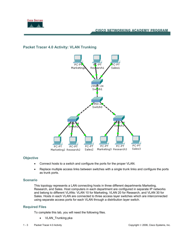
Packet Tracer 4.0 Activity: VLAN Trunking Objective Connect hosts to a switch and configure the ports for the proper VLAN. Replace multiple access links between switches with a single trunk links and configure the ports as trunk ports. Scenario This topology represents a LAN connecting hosts in three different departments Marketing, Research, and Sales. Host computers in each department are configured in separate IP networks and belong to different VLANs: VLAN 10 for Marketing, VLAN 20 for Research, and VLAN 30 for Sales. Hosts in each VLAN are connected to three access layer switches which are interconnected using separate access ports for each VLAN through a distribution layer switch. Required Files To complete this lab, you will need the following files. 1-3 VLAN_Trunking.pka Packet Tracer 4.0 Activity Copyright 2006, Cisco Systems, Inc. Plan: Familiarize yourself with PT 4.0 help menu, in case you have questions. Open VLAN_Trunking.pka and follow the Instructions, which are repeated below: Act: Step 1 Examine the current network configuration. a. Examine the IP address of the host computers. b. How many IP networks are there? _________________________________________________ c. What is the network address of the following departments? Marketing ____________________________________________________________________ Research ____________________________________________________________________ Sales ________________________________________________________________________ d. On each switch issue the commands show running-config and show vlan, examine the output and complete the following table. Department VLAN number Ports on Switch0 Ports on Switch1 Ports on Switch2 Ports on Switch3 Marketing Research Sales Step 2 Connect additional hosts to the network. a. Connect host Sales2 to Switch2 port Fa0/6 and configure the port for the proper VLAN. b. Connect host Research3 to Switch3 port Fa0/5 and configure the port for the proper VLAN. Step 3 Verify connectivity. a. Ping from every host to the other two hosts in the same department. b. Were the pings successful? ______________________________________________________ c. Ping from Marketing1 to Sales3. d. Was the ping successful? ______ Why not? _________________________________________ Step 4 Replace the multiple access links between the switches with single trunk links. a. The switches are currently connected by three access links, one for each VLAN. A trunk link can carry frames for multiple VLANs over a single link, freeing up switch ports and reducing the number of required links. 2-3 Packet Tracer 4.0 Activity Copyright 2006, Cisco Systems, Inc. b. If the access links between the switches were replaced by a single trunk link between each access switch (Switch1, Switch2, and Switch3) and the distribution switch (Switch0), how many switch ports would be freed up? _____________________________________________________________________________ c. The dashed links between the switches represent three crossover cables stacked over each other. Click the Delete tool on the Common Tools Bar (the red X on the far right) and click one of the links between the switches to remove it. Repeat the process to remove the second link between the same two switches. Using the same procedure, remove two links between the remaining switches. You will be left with a single crossover link between Fa0/1 on Switch0 and Fa0/1 on Switch1, a single crossover link between Fa0/4 on Switch0 and Fa0/1 on Switch2, and a single crossover link between Fa0/7 on Switch0 and Fa0/1 on Switch3. If you removed a link in error, replace it. d. Configure the switch ports at either end of the remaining crossover cables as trunk ports. Step 5 Verify connectivity in the modified network. a. Ping from every host to the other two hosts in the same department. b. Were the pings successful? ______________________________________________________ c. 3-3 Verify your configuration by clicking the Check Results button. Packet Tracer 4.0 Activity Copyright 2006, Cisco Systems, Inc.


