EE101 Lab 7 microcontroller install
advertisement
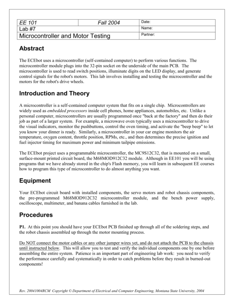
EE 101 Lab #7 Fall 2004 Microcontroller and Motor Testing Date: Name: Partner: Abstract The ECEbot uses a microcontroller (self-contained computer) to perform various functions. The microcontroller module plugs into the 32-pin socket on the underside of the main PCB. The microcontroller is used to read switch positions, illuminate digits on the LED display, and generate control signals for the robot's motors. This lab involves installing and testing the microcontroller and the motors for the robot's drive wheels. Introduction and Theory A microcontroller is a self-contained computer system that fits on a single chip. Microcontrollers are widely used as embedded processors inside cell phones, home appliances, automobiles, etc. Unlike a personal computer, microcontrollers are usually programmed once "back at the factory" and then do their job as part of a larger system. For example, a microwave oven typically uses a microcontroller to drive the visual indicators, monitor the pushbuttons, control the oven timing, and activate the "beep beep" to let you know your dinner is ready. Similarly, a microcontroller in your car engine monitors the air temperature, oxygen content, throttle position, RPMs, etc., and then determines the precise ignition and fuel injector timing for maximum power and minimum tailpipe emissions. The ECEbot project uses a programmable microcontroller, the MC9S12C32, that is mounted on a small, surface-mount printed circuit board, the M68MOD912C32 module. Although in EE101 you will be using programs that we have already stored in the chip's Flash memory, you will learn in subsequent EE courses how to program this type of microcontroller to do almost anything you want. Equipment Your ECEbot circuit board with installed components, the servo motors and robot chassis components, the pre-programmed M68MOD912C32 microcontroller module, and the bench power supply, oscilloscope, multimeter, and banana cables furnished in the lab. Procedures P1. At this point you should have your ECEbot PCB finished up through all of the soldering steps, and the robot chassis assembled up through the motor mounting process. Do NOT connect the motor cables or any other jumper wires yet, and do not attach the PCB to the chassis until instructed below. This will allow you to test and verify the individual components one by one before assembling the entire system. Patience is an important part of engineering lab work: you need to verify the performance carefully and systematically in order to catch problems before they result in burned-out components! Rev. 20041004RCM Copyright © Department of Electrical and Computer Engineering, Montana State University, 2004 7-2 First, make sure all 8 of the DIP switches are in the OFF position. If any are 'on,' use a plastic screwdriver (or your fingernail) to gently switch them to the off position. Your PCB should have two 2-pin shorting jumpers installed. Check to see that: In the lower right corner of the board, the red jumper is installed on JP1 just to the right of the voltage regulator. In the far right part of the board, a black jumper is installed on the 2-pin header just to the left of the potentiometer. Shorting jumper next to R17 Power 'on' LED (Red) Shorting jumper on JP1 Power connector (Plug) (Black) Set the DC bench supply to +12 volts using the DMM. Place a power pigtail connector on the SV11 header just to the left of the voltage regulator, and apply the +12V (red) to the top wire and the black supply connection to the bottom wire. The red power indicator LED (LED1, lower left corner of the board) should be illuminated. If not, turn of the power immediately and check your connections. 7-3 P2. Now TURN OFF THE DC BENCH SUPPLY. Make sure the power LED on the PCB is OFF. NEVER INSTALL OR REMOVE COMPONENTS WITH THE POWER ON!! With power still OFF, turn the board over so you can get at the 32-pin socket on the back side. Orient the board so that 7-segment display resistors are toward the top of the board and the index notch on the socket is to the left. Discharge yourself of static electricity by touching your finger on the ground tab on the oscilloscope. Set the 32-pin microcontroller module loosely onto the socket, pin 1 (white square) to the lower left and the run/boot switch to the right (the printed labels on the module will be upside down—this is OK). Make sure that it is oriented correctly and that all of the pins are lined up with the receptacles. Have your instructor or TA verify the orientation before carefully seating the module down into the socket. Microcontroller positioned correctly: Instructor/TA initials IT IS EASY TO BEND THE PINS ACCIDENTALLY, so be certain that each pin is going into the mating receptacle! Put the RUN/BOOT switch on the module into the RUN position (slide the switch toward the bottom edge of the board), then turn the board over and rest it softly on the bench top. Verify that the DC Bench Supply is set for +12 volts, and then reconnect the power to the PCB. The microcontroller should now be running! Look for the following: The power indicator LED (LED1, lower left) is illuminated The side LEDs (LED2, left, and LED3, right) are blinking slowly on and off The 4-digit LED display should say "COOL" and then do a test of each segment Note any malfunctions: immediately turn of the power and consult the instructor or your lab TA for help. P3. Using a plastic screwdriver or your fingernail, gently slide the number 5 DIP switch to the 'on' position. Leave the other seven switches in the off position. Then press and release the RESET button (lower left corner). This causes the microcontroller to generate two control signals to the 3-pin headers with labels 'sig', 'pwr', and 'gnd' located on the left and right sides on the front of the PCB near the lower side mounting holes. Connect CH1 of the oscilloscope to observe the waveform on the left 'sig' (top) pin, and connect CH2 of the scope to observe the right 'sig' pin. Adjust the scope to view both waveforms simultaneously on the screen. YOU WILL PROBABLY HAVE TO SWITCH THE TRIGGER SOURCE FROM ONE CHANNEL TO THE OTHER TO GET A STABLE DISPLAY. 7-4 Determine the frequency and duty cycle of the two waveforms. Describe, using complete sentences, what is similar and what is different about the two signals. Also, sketch the two signals on the same scale. P4. Now disconnect the oscilloscope and turn the power off from the DC bench supply. Mount the PCB onto the top of the chassis U-brackets using the ¾" screws and ½" tubular spacers so that the 4-digit display is toward the front and the voltage regulator is toward the back (over the caster). Use the holes in the U-bracket as shown here: 4-digit Display Jiggle the orientation until the screws and bracket holes line up. Gently tighten the mounting screws just until they are snug. Caster (below) With the power still OFF, slide the 3-pin connector cable from the right motor onto the PCB's right side 3-pin (sig, pwr, gnd) motor control header WITH THE WHITE WIRE TOWARD THE TOP OF THE PCB (white = sig, red=pwr, black=gnd). Do the same for the left side motor cable, again ensuring that the connector has the white wire toward the top of the board. 7-5 Battery Pack: Your robot will run properly with only seven batteries if the batteries are fresh. Seven batteries (nominal 10.5 volts) will also help minimize wasted power in the 7805 voltage regulator chip. First, make a jumper wire about 7 cm long with stripped ends. Next, pick up the battery holder so that the red and black wires emerge from the top left (see below). Install only two batteries in the side facing you, one in the left position and one in the right, and install all 5 batteries on the back side. Red and black wires Jumper wire (stripped ends snug under springs) (and 5 batteries on the back side) Battery here … …and a battery here no batteries in these 3 positions Finally, insert one end of the jumper wire under the upper left spring so it makes good electrical contact, and place the other end of the jumper wire under the lower right spring. You now have a “stack” of seven batteries instead of ten. Use the DMM to measure the voltage at the battery connector: it should be approximately 10.5 volts. Make sure the DIP switch number 5 is still 'on' and the other switches are in the 'off' position. Hold the robot up off the bench so the wheels are free to rotate and not touching anything. To test the motors, slide the 4-pin power cable from the battery pack onto the power input header and push the reset button. The wheels should start to rotate. If the power indicator LED does not come on or if the motors do not rotate, disconnect the battery pack immediately and carefully recheck the connections. To stop the wheels, disconnect the battery connector. 7-6 P5. If the motors appear to be functioning properly, mount the battery pack in between the motors and toward the rear caster on the chassis plate using a Velcro strip or some tape. You are now ready to try the following three built-in test programs. (1) 5 seconds forward test: First, find an open space in the lab or out in the hallway and set your ECEbot on the floor. For this test, turn DIP switch number 2 to the 'on' position and make sure all of the other DIP switches are in the OFF position. Connect the battery power cable. The robot should move forward for about 5 seconds and then automatically stop. To repeat the test, reposition the robot and press the RESET button. (2) Forward/Backward test: Turn DIP switch number 3 to the 'on' position and make sure all of the other DIP switches are in the 'off' position. Press the RESET button. The robot should move forward and backward a short distance over and over continuously until you disconnect the battery cable. (3) ECEbot dance test: Turn DIP switch number 4 to the 'on' position and make sure all of the other DIP switches are in the 'off' position. Press the RESET button. The robot should do a sequence of movements and turns over and over endlessly until you disconnect the battery cable. When you have completed the tests, be sure to disconnect the battery cable to keep the batteries from running down. LEFT SENSOR AnaIn S1 Gnd S2 5v SV4 +5V (yellow) SV9 (to Left Sensor Board) SV6 P6. As the final assembly step, locate the LEFT SENSOR and RIGHT SENSOR areas of the PCB. The 4-pin connector from the left and right bumpers will connect to header SV9 and SV10, respectively. DigIn RIGHT SENSOR DigIn SV5 AnaIn S1 Gnd S2 5v SV10 SV7 MAKE SURE that the 4-pin connector is oriented properly so that the +5V (Yellow) wires are toward the rear of the robot (matching the silk screen). (to Right Sensor Board) +5V (yellow) 7-7 Test the bumper switches by running a single jumper wire from the S2 pin of header SV4 (left) up to either pin of the 2-pin header near LED4, and from the S2 pin of header SV5 (right) up to the 2-pin header below LED5. Connect the battery cable and verify that LED4 lights when you press the left front bumper switch and LED5 lights when you press the right front bumper switch. Ask your instructor/TA for assistance if this does not work. (to Left Sensor Board) (to Left Motor) (to Right Sensor Board) (to Right Motor) Once the bumper switches check out, change the 1-pin connector wires so that they go from the S2 pins in the SV4 and SV5 headers to the adjacent DigIn pins in the sensor area of the PCB. This sends the bumper signal to one of the input ports on the microcontroller. (to Left Sensor Board) (to Left Motor) (to Right Sensor Board) (to Right Motor) 7-8 Select program 4 (dance mode) using the DIP switch and hit the reset button. The microcontroller is also monitoring the bumper switches: if you hit either switch, the robot should stop. If not, you need to check the switch connections, cables, and connections. Seek help from the instructor/TA if necessary. Finally, run program 5 ("bump-back-turn") to make sure your robot is functional with its bumper switches: your robot should move forward until one of the switches hits an object. If the left switch is hit the robot should stop, back up, and turn right. On the other hand, if the right switch is hit the robot should stop, back up, and turn left. Try this out in the hallway. Motor and switch inspection: Instructor/TA initials Congratulations if you (and your robot) have made it this far. Excellent! Next week is the lab practical exam. Good luck!
