Solutions to Review Questions
advertisement
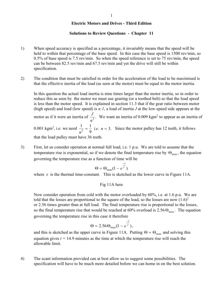
1 Electric Motors and Drives - Third Edition Solutions to Review Questions - Chapter 11 1) When speed accuracy is specified as a percentage, it invariably means that the speed will be held to within that percentage of the base speed. In this case the base speed is 1500 rev/min, so 0.5% of base speed is 7.5 rev/min. So when the speed reference is set to 75 rev/min, the speed can be between 82.5 rev/min and 67.5 rev/min and yet the drive will still be within specification. 2) The condition that must be satisfied in order for the acceleration of the load to be maximised is that the effective inertia of the load (as seen at the motor) must be equal to the motor inertia. In this question the actual load inertia is nine times larger than the motor inertia, so in order to reduce this as seen by the motor we must use gearing (or a toothed belt) so that the load speed is less than the motor speed. It is explained in section 11.3 that if the gear ratio between motor (high speed) and load (low speed) is n:1, a load of inertia J at the low-speed side appears at the J motor as if it were an inertia of 2 . We want an inertia of 0.009 kgm2 to appear as an inertia of n 1 1 0.001 kgm2, i.e. we need 2 i.e. n 3. Since the motor pulley has 12 teeth, it follows 9 n that the load pulley must have 36 teeth. 3) First, let us consider operation at normal full load, i.e. 1 p.u. We are told to assume that the temperature rise is exponential, so if we denote the final temperature rise by max , the equation governing the temperature rise as a function of time will be t max (1 e ) where is the thermal time-constant. This is sketched as the lower curve in Figure 11A. Fig 11A here Now consider operation from cold with the motor overloaded by 60%, i.e. at 1.6 p.u. We are told that the losses are proportional to the square of the load, so the losses are now (1.6)2 or 2.56 times greater than at full load. The final temperature rise is proportional to the losses, so the final temperature rise that would be reached at 60% overload is 2.56 max . The equation governing the temperature rise in this case it therefore t 2.56 max (1 e ) , and this is sketched as the upper curve in Figure 11A. Putting max and solving this equation gives t = 14.9 minutes as the time at which the temperature rise will reach the allowable limit. 4) The scant information provided can at best allow us to suggest some possibilities. The specification will have to be much more detailed before we can home in on the best solution. 2 Nevertheless there is information that provides useful guidance, particularly as a direct drive (i.e. no gearbox) is specified. Full torque is required at all speeds, and since we know that the maximum power is about 1200 W at 10,000 rev/min, the torque is a modest 1.1 Nm. The torque of a machine will usually give an idea of its volume, but if we have little experience we can still get some idea by noting that at the more commonplace speed of say 2000 rev/min, the output power will only be 240 W. So we might expect the size of the motor to be comparable to say a medium-range hand-held power drill. The top speed of 10,000 rev/min is on the high side, and immediately limits the choice of motor/drive. Conventional (brushed) d.c. machines are seldom expected to run at speeds as high as this because of difficulties with commutation. A standard 2-pole induction motor could not be expected to run happily at 10,000 rev/min when its bearings and rotor design were intended for a maximum of 3600 rev/min. An off the shelf induction motor aimed at the inverter-fed market would also probably have an upper limit of something like twice mainsfrequency speed, so a special would be required to allow speeds of 10,000 rev/min. In short, we should not expect to be able to do this job with a run-of-the-mill motor, and instead we must expect to move into the specialist area and face the inevitable higher cost. Our best bet will probably be a totally-enclosed brushless d.c. motor/drive designed specifically to meet the high speed. The minimum frequency at which the stator windings will be switched will be 167 Hz, which will mean that special low-loss steel will be required in order to minimise iron losses. Further matters that will have a bearing on the selection include the space available ( a short fat motor or a long thin one?); the required accuracy of speed holding; the dynamic performance (i.e. what is the required bandwidth of the speed control loop); the stall protection requirements; the operating environment (will the motor have to withstand cutting fluids?, what is the ambient temperature range); the mounting and coupling arrangements (which can be surprisingly tricky for a direct drive); and maybe several more! 5) As far as the hoist motor is concerned, the load on the hook directly determines the steady-state torque. The maximum weight that may be attached to the hook is specified on the hoist, and it is understood that this limit is not related to the hoisting speed. It follows that full motor torque must be available at all speeds. When speed control using an inverter becomes available, the operator may set the drive to lift the maximum load at a slow speed, the motor then drawing full current in order to produce full torque. In this condition the motor losses will be high but because of the low speed the cooling fan will be much less effective than at full speed and prolonged operation will therefore result in the motor overheating. The remedy will be to fit a cooling blower, or an oversized motor. 6) Controlled-speed applications for which conventional (brushed) d.c. motors are not well-suited include:a) Any application in an environment where there is a danger of explosive gases being present, because of the danger of ignition caused by sparking of the commutator. The obvious area where this applies is in mining, where inverter-fed induction motors are inherently less dangerous (though they will also have to have flameproof enclosures). 3 b) Any application where it is essential to minimise periodic maintenance, such as unmanned off-shore installations. The conventional d.c. motor requires regular inspection and renewal of brushes, so again an inverter-fed induction motor is likely to be preferred. c) Applications requiring large numbers of motors to run at precisely the same speed, such as textile and process lines. Major cost savings are achieved with synchronous or reluctance motors supplied from a single inverter, compared with the closed-loop speed control that would be required for every d.c. motor. 7) This question relates to the rating of motors performing an intermittent duty, which was discussed in section 11.4.2. The general approach is to rate the motor according to the r.m.s. of its power cycle, on the assumption that the losses (and therefore the temperature rise) vary with the square of the load. The waveforms of power vs time and (power)2 vs time are sketched in Figure 11B. Fig 11B here 4 1 0 1 2 (kW) 2 , 2 so the root mean square power is 1.4 kW, and this is therefore the appropriate continuous fullload rating for the motor. The mean of the power squared plot is given by:- Mean of (Power) 2 8) This is another cyclic loading problem, so we begin by estimating the r.m.s. output power. For the one minute that the motor runs on load the torque is 60 Nm and the speed 1400 rev/min, so 2 8,800 W or 8.8 kW. For the following the power output is given by Pout 60 1400 60 five minutes the motor runs light so the output power is zero. The power-squared plot is therefore as shown in Figure 11C. Fig 11C here The mean of the power squared plot is given by:77.44 1 0 5 Mean of (Power) 2 12.9 (kW) 2 , so the root mean square is 3.6 kW. 6 The periods of operation are certainly short in comparison with the thermal time-constant, so on the basis of the continuous power rating we could choose the 4 kW, motor. But we need to check that it would have sufficient torque during the one-minute periods i.e. 60 Nm. We are told that the pull-out torque will be 200% or 2 p.u., i.e. the pull-out torque is twice the full-load torque. We can calculate the full-load torque by dividing the output power by the running speed. Clearly, since the supply is 50 Hz, we will choose a 4-pole motor (synchronous speed = 1500 rev/min): given that the full-load slip is about 5%, we can assume that the fullload speed is 1500 0.95, i.e. 1425 rev/min, close enough to the desired speed. So the rated 4 4000 26.8 Nm. So now we know that the 2 1425 60 pull-out torque of the 4 kW motor is 2 26.8 = 53.6 Nm. This is insufficient to meet the requirement of 60 Nm, so a 4 kW motor will not be suitable and we must go for the next one up, i.e. 5.5. kW. torque of the 4 kW motor is given by T f l The full-load torque of the 5.5 kW motor turns out to be 36.9 Nm, so its peak torque is almost 74 Nm, which provides a good margin over the 60 Nm we are seeking to drive the pump. The rated torque of 36.9 Nm is obtained at a speed of 1425 rev/min, i.e. a slip of 75 rev/min. We are asked to estimate the running speed at 60 Nm, so all we can do is to assume that the torque remains proportional to slip, in which case the slip at 60 Nm will be given by 60 s 75 122 rev/min. The running speed will therefore be 1500 - 122 = 1378 rev/min, 36.9 which satisfies the requirement that the running speed should be approximately 1400 rev/min. 9) When the speed reference is set at 100% and the drive is at rest, the drive will apply full torque to accelerate as fast as possible. In most drives, full torque will be maintained until the speed comes within a few percent of the target, and only then will the torque be reduced to give a smooth approach to the final speed. The information we are given is in line with normal behaviour, because we are told that the acceleration up to 1180 rev/min is more-or-less uniform, which means that the nett torque remains constant. However, we are asked to estimate the system inertia, so we need to make use of the dynamic equation, i.e. torque = inertia angular acceleration. But although we can calculate the rated torque of the motor, and assume that this remains constant during run-up, we have no information about friction torque, so all we can do is to make the reasonable assumption that it is small in comparison with the motor torque, and ignore it. 50 103 398 Nm. The angular acceleration The rated torque of the motor is given by T 2 1200 60 2 (1180 0) d 60 30.9 rad/ sec2 . Hence the inertia is given by is given by dt 4 398 J 12.9 kgm 2 . 30.9 To find the stored kinetic energy at full speed we use the expression 1 1 1200 2 E J 2 , i.e. E 12.9 101.85 kJ. 2 2 60 2 We could find the energy supplied in the first 4 seconds by repeating the calculation above with a speed of 1180 rev/min, but the point of this part of the question is to encourage us to recognise 5 that when acceleration takes place at constant torque, the speed increases linearly with time and so therefore does the output power of the motor (because power = torque times speed, and torque is constant). The average power in this case is therefore half of the power at 4 seconds, 1180 50 49.17 kW. So the average power is 0.5 49.17 = 24.58 kW. which in turn is 1180 1200 The energy supplied is thus given by the average power times the time, i.e. 24.58 kW 4 sec = 98.33 kJ. The extra 3.5 kJ represents the additional kinetic energy gained during the final part of the runup from 1180 to 1200 rev/min. During this time the speed controller will not be saturated, and the torque will taper-off as the final speed is approached. 10) When the motor (see question 9) is switched off completely, the only torque will be that due to friction, and because we know the total inertia we can estimate the friction torque if we know the deceleration. The speed falls from 1200 rev/min to 1080 rev/min in 20 seconds so the angular deceleration is 2 1200 1080 60 0.63 rad / sec2 . We know that the corresponding acceleration given by 20 under full motor torque is 30.9 rad/sec2, so we can express the magnitude of the friction torque as a fraction of the full-load torque as 0.63/30.9 = 0.02. In other words the friction torque is about 2% of the full-load torque, which justifies our neglect of friction in answering question 9. - End of Solutions Chapter 11 -


