The Oscilloscope: General Feature
Experiment # 05
The Oscilloscope: General Features
Object:
Students should become familiar with the oscilloscope.
Learn how to use most of its functions.
Check the voltage and time base calibrations.
Measure the phase difference between two sinusoidal signals.
Apparatus:
Oscilloscope.
Functions generator.
DC power supply (0-20V).
Resistor decade box.
Multimeter.
Different capacitors.
Experimental set-up and procedure:
I. Calibration a) Tim base calibration
1. Set the oscilloscope to the following functions:
Chop (to see both channel 1 and 2)
Set the trigger on AUTO and the trigger source on channel 1
2. Connect the function generator output to the vertical input (channel 1) of the oscilloscope and observe the following functions: sine, square, and triangular waves of several different frequencies.
Important: Adjust the trigger level, vertical scale, and the time base to see a stable signal
3. Apply a sinusoidal voltage with a frequency f to channel 1
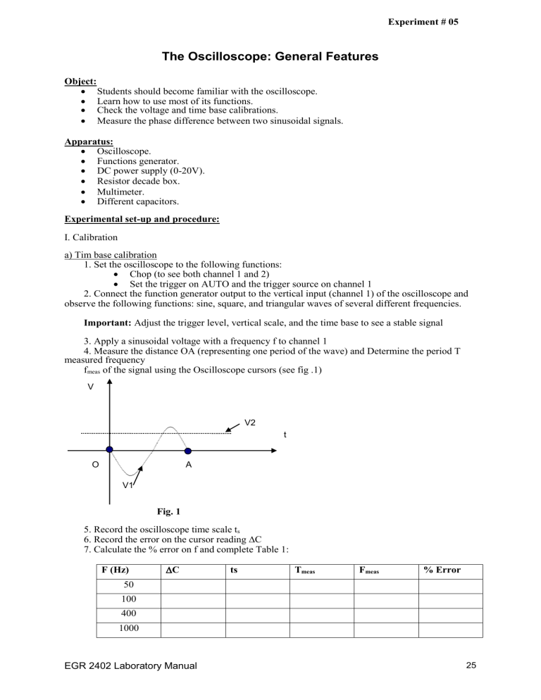
4. Measure the distance OA (representing one period of the wave) and Determine the period T measured frequency f meas
of the signal using the Oscilloscope cursors (see fig .1)
V
V2 t
O A
V1
Fig. 1
5. Record the oscilloscope time scale t s
6. Record the error on the cursor reading
C
7. Calculate the % error on f and complete Table 1:
F (Hz)
C ts T meas
50
100
400
1000
EGR 2402 Laboratory Manual
F meas
% Error
25
8. Is the oscilloscope sweep-speed (or time base) calibrated? Explain why b) Voltage calibration:
1. Disconnect every thing from the oscilloscope
2. Adjust the vertical position of the trace to be exactly on the time axis and note this position as zero Volts (see Fig. 1)
Important: You should repeat step 1 and 2 each time you adjusted the vertical or horizontal position on the scope
3. Connect a DC voltage source to channel 1 of the oscilloscope and apply different voltages U
4. Measure the distance OB using the cursors and determine the voltage measured with the oscilloscope V osc
at each value of U (see Fig. 1)
5. Record the vertical scale Vs
6. Record the error on the cursor reading
C
7. Measure these values of U using a voltmeter and record them under V meter
8. Calculate the % difference between V osc and V meter
9. Record all your values in Table II :
U(Volts)
C V s
V osc
V meter
% difference
2
5
10
20
10. Is the oscilloscope voltage axis (vertical scale) calibrated?
11. What could be the major source of error?
II. Phase Measurements:
Set up the circuit in Fig. 2
Important: Do not close the switch S until your instructor verifies your circuit
Ch2
Oscillo
C
Ch1
S
Fig.2
R
With: I= I o sin(wt) , V
1
= RI
0
sin(wt) and V
2
= ZI
0
sin (wt-
)
Where V
1
is the voltage across R and V
2 is the voltage across R and C, Z is the impedance of the circuit and
is the phase difference between the two sinusoidal potentials V section is to measure
using two different methods:
1
and V
2
The goal in this a) Direct method
1.Set the frequency generator to the different frequencies f given in Table III
2.Connect V
1
and V
2
respectively to channels 1 and 2 of the oscilloscope
3.Measure the period T of the signal at the different values of f
4.Measure the time difference t as shown in the schematic figure below:
EGR 2402 Laboratory Manual 26
V
1
V
2
Fig.3
5. The phase difference
between the two sinusoidal voltages V
= - 360
/ T
6. Determine
and the % error on
1
and V
2
is given by
7. Record all your values in Table III : f (Hz) T
% Error
50
100
400
1000
8. Does
depend on the frequency f? Explain why?
X b) Ellipse method:
C
A
O B
D
X
Fig.4
Important: in order to reduce the measurements errors:
Make sure that V
1
and V
2
are well centered with respect to the x-axis and that the ellipse is well centered with respect to the origin O.
Chose the time base that will give you the largest ellipse on the oscilloscope screen
1. The experimental set-up stays the same as in part a).
2. Set the oscilloscope time base to the position ‘XY’.
3. Measure the distances AB and CD as shown in Fig. 4.
4. Determine the phase difference
' between V
1
and V
2
knowing that it is given by the following
Relation: sin
' = AB/CD.
5. Calculate the % error on
' and explain how you did that?
6. Change the frequency f and repeat steps 3 and 4
7. Record all your values in Table IV:
EGR 2402 Laboratory Manual 27
f(Hz)
50
AB CD
’ % Error
100
400
1000
8. Does the ellipse size depend on f? What about
' does it depend on f? Explain.
Conclusions:
1. Compare the measured values of
and
’ and discuss which method is more precise for the phase measurements.
2. Summarize what you have learned from these experiments
EGR 2402 Laboratory Manual 28
Name:
Section:
I. Calibrations a) Time base calibration f (Hz)
50
The Oscilloscope: General Feature
C ts T meas
100
400
1000
% Error
Experiment #05 b) Voltage calibration
U (Volts)
2
5
10
20
II. Phase Measurements a) Direct method f (Hz)
50
100
400
1000 b) Ellipse method f (Hz)
50
100
400
1000
C
C
AB
V s t s
CD
V osc
T meas
’
V meter
% Error
% Error
%Difference
EGR 2402 Laboratory Manual 29


