Chapter 7
advertisement
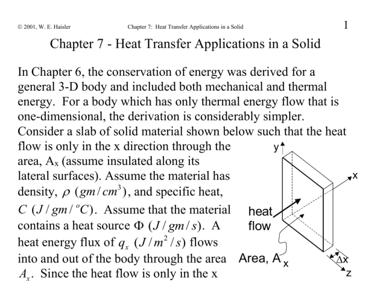
2001, W. E. Haisler Chapter 7: Heat Transfer Applications in a Solid 1 Chapter 7 - Heat Transfer Applications in a Solid In Chapter 6, the conservation of energy was derived for a general 3-D body and included both mechanical and thermal energy. For a body which has only thermal energy flow that is one-dimensional, the derivation is considerably simpler. Consider a slab of solid material shown below such that the heat flow is only in the x direction through the y area, Ax (assume insulated along its x lateral surfaces). Assume the material has density, ( gm / cm3 ) , and specific heat, C ( J / gm / oC ) . Assume that the material heat contains a heat source ( J / gm / s). A flow heat energy flux of qx ( J / m2 / s) flows into and out of the body through the area Area, A x x z Ax . Since the heat flow is only in the x 2001, W. E. Haisler 2 Chapter 7: Heat Transfer Applications in a Solid direction, the temperature T is a function of x only. Conservation of thermal energy requires: accumulation of thermal energy (J) contained in the system for the time period thermal energy (J) entering the system during the time period thermal energy (J) net generation of leaving the system thermal energy (J) in during the time the system during period time time period C ˆ T y x heat flow Area, A x ˆ T Ax x C t t t qx x Ax t qx x x Ax t Ax xt x z 2001, W. E. Haisler Chapter 7: Heat Transfer Applications in a Solid 3 Note that each term in the above has units of J. Dividing by Ax xt and taking the limit as x, t 0 gives T qx Ĉ t x 1-D Conservation of thermal energy, Heat Transfer in a Solid Note that T=T(x,t). We have 1 governing PDE (Conservation of Energy) and 2 unknowns (T and q x ). We need another equation! 2001, W. E. Haisler Chapter 7: Heat Transfer Applications in a Solid 4 For the static case (no mass velocity, v 0 ), Conservation of Energy in 3-D becomes: C T q Heat Conduction in Solid t Unknowns: T T ( x, y, z, t ) =temperature q ( x, y, z, t ) qxi q y j qz k is the heat flux vector (W/m2) Known: C is the specific heat of the material, is mass density. ( x, y, z ) =heat source (W/kg). Notice that we have 1 governing PDE but there are a total of 4 unknowns (T, q x , q y , q y )!! And they are functions of x, y, z, and t. 2001, W. E. Haisler 5 Chapter 7: Heat Transfer Applications in a Solid We need 3 more equations. Fourier made an experimental observation which relates temperature (T) and heat flux (q). For the case of heat flow in one direction only (say x direction), he observed that the heat flux was proportional to the negative of the temperature gradient: qx wall qx T1 T2 dT qx k dx k dT T2 T1 dx L dT L x dx The proportionality constant k is called the coefficient of thermal conductivity and is an experimental material "constant." Units: k T has units of J/(m sec K) = W/(m K). The equation q k x x is called a constitutive relation because it relates certain o o 2001, W. E. Haisler Chapter 7: Heat Transfer Applications in a Solid 6 variables by a material property. For an isotropic material (same properties in all directions), we find experimentally T T T that q k , q k , and q k q k T x z x y z y For the general 3-D case, Fourier’s law of heat conduction states that the heat flux due to conduction is proportional to the negative of the temperature gradient. Negative in above indicates that positive temperature gradient produces negative heat flux (heat flow from hot to cold). With Fourier’s law: C T (kT ) . t If k does not vary spatially, then (kT ) k (T ) k 2T 2001, W. E. Haisler Chapter 7: Heat Transfer Applications in a Solid 7 2 2 2 where 2 x2 y 2 z 2 2T 2T 2T and 2T x2 y 2 z 2 Heat transfer equation becomes C T k 2T for constant k t For steady state-heat conduction (no variation with time) k2T 0 Steady-state, constant k d 2T d 2T 1-D, steady-state, constant k k 2 0 2 dx k dx 2001, W. E. Haisler 8 Chapter 7: Heat Transfer Applications in a Solid The previous differential equations for heat transfer in a solid require knowledge of: Boundary Conditions (values of temperature, T; or the heat flux on the boundary): n 1) T TS ( x, y, z , t ) Types of B.C. 1) specified temperature 2) specified heat flux 3) convection 2) n q constant 3) n q h(T T ) s TS T Note:T is the temperature of the environment 2001, W. E. Haisler Chapter 7: Heat Transfer Applications in a Solid 1. Specified surface temperature, T(x,y,z,t)=TS(x,y,z,t) 2. Specified heat flux on surface with unit outward normal n : n q n (kT ) known / given function( x, y, z, t ) nq 0 (special case of insulated boundary) 3. Specified heat flux due to convective heat transfer: n q h(T T ) s where T = surface temperature (unknown) s T = far-field temperature (specified/known) h = heat transfer coefficient (from experiment) Note: h has units of J/(m2 sec oK) = W/(m2 oK). 9 2001, W. E. Haisler 10 Chapter 7: Heat Transfer Applications in a Solid Difference between Conduction and Convection Conduction Occurs in a Solid Relates heat flux q x to temperature gradient in solid T1 solid qx dT T2 T1 dx L Convection Occurs in a Fluid (say, air) Relates heat flux q x to temperature difference in fluid air solid qx TS T2 T L x x T TS T qx qx k k dT dx dT dx qx q x h (TS T ) h TS T 2001, W. E. Haisler Chapter 7: Heat Transfer Applications in a Solid 11 Both are assumptions verified by experiment Both "laws" contain experimentally obtained material "constants" Note: AT the boundary between a solid and a fluid, heat flux must be the same. Therefore, on a boundary whose unit outward normal is i (as shown above): qx ( solid ) qx ( fluid ) dT k dx h(TS T ) h(T TS ) surface solid dT dx fluid TS T 2001, W. E. Haisler 12 Chapter 7: Heat Transfer Applications in a Solid Example: 1-D, Steady-state heat conduction in an insulated bar with specified temperatures on ends of bar (TL and TR, as shown): GEOMETRY AND BOUNDARY CONDITIONS y insulated, q y =0 a x TL b TR L z insulated, q =0 z The heat conduction equation reduces to 2T 0 or 2T 2T 2T 0 x2 y 2 z 2 2001, W. E. Haisler Chapter 7: Heat Transfer Applications in a Solid Insulated B.C. on lateral surfaces T y=a/2, q k 0 T T ( y) , y y T 0 T T ( z) z=a/2, q k z z This implies heat flow only in x direction so that the heat 2T d 2T 0. conduction equation reduces to x 2 dx 2 Solving the heat conduction equation gives T ( x) C x C 1 2 Apply temperature B.C. on end surfaces 13 2001, W. E. Haisler at x 0: T ( x) C x C Chapter 7: Heat Transfer Applications in a Solid T (0) T C (0) C 2 L 1 1 2 14 C T 2 L T (L) T C L C 2 R 1 T C L T C (T T )/ L R 1 L 1 R L Substituting constants of integration back into T(x) gives the solution for T(x) as TR TL T ( x) TL x L at x L : If the temperature at the left end is TL=45C and the right 35C 45C end, TR=35C, and L=1 m; then T ( x) 45C x 1m Or, T ( x) 45C (10C / m) x (a linear function in x) The heat flux in the bar is given by 2001, W. E. Haisler Chapter 7: Heat Transfer Applications in a Solid 15 dT dT dT TR TL q k k ( i j k k i dx dy dz L If the temperature at the left end is TL=45C and the right end, TR=35C, L=1m; and the bar is made of aluminum with k=247 W/(m-C), then the heat flux is given by TR TL J 35C 45C q k i 247 i 2, 470(W / m 2 )i L msC 1m 2.47( kW / m 2 )i Note that the heat flux is positive, i.e., to the right (since the bar is cooler on the right). 2001, W. E. Haisler Chapter 7: Heat Transfer Applications in a Solid 16 Another Example: Suppose the bar above contained a constant heat source of 5W / cm3, a=b=2 cm, L=1 m and the bar is made of aluminum with a thermal conductivity of k=247 W/m/C. The temperature at the left end is TL=45C and the right end, TR=35C. Determine T(x) in the bar. Assuming steady state, the heat transfer equation is given by d 2T d 2T k / k or dx 2 dx 2 For this case, 5W / cm3 5kW / m3 (a constant). The ODE becomes d 2T 5kW / m3 o 2 / k 20.243( C / m ) 2 dx 247W /(mC ) Integrating the ODE twice gives: T ( x) 10.121( oC / m2 ) x 2 C1x C2 2001, W. E. Haisler Chapter 7: Heat Transfer Applications in a Solid Applying the boundary conditions: At x=0m: 17 T ( x) 10.121( oC / m2 ) x 2 C1x C2 T (0) 45 oC 10.121( oC / m 2 )(0) 2 C1 (0) C2 C2 45 oC At x=1m: T (1m) 35 oC 10.121( oC / m 2 )(1m) 2 C1 (1m) C2 35 oC 10.121( oC / m 2 )(1m) 2 C1 (1m) 45 oC C1 0.121( oC / m) Substituting the constants of integration into T(x) gives: T ( x) 10.121( oC / m 2 ) x 2 0.121( oC / m) x 45 oC Note that for a constant heat flux , the temperature distribution is quadratic in x. 2001, W. E. Haisler Chapter 7: Heat Transfer Applications in a Solid The heat flux becomes 45 oC 18 35 oC x dT qx k 247(W /(mC )) 20.242( oC / m 2 ) x 0.121( oC / m) dx at x=0 m: qx 29.9(W / m2 ) (to left) x=0.5 m: qx 2, 470(W / m2 ) (to right) x=1 m: qx 4,970(W / m2 ) (to right) Note: W=J/s Question: Why is heat flowing to the left at x=0 even though the bar is hotter on the left end compared to the right end (and therefore you might expect heat flow from left to right)? 2001, W. E. Haisler 19 Chapter 7: Heat Transfer Applications in a Solid If we increase to 10kW / m3 , the solution becomes: T ( x) 20.242( oC / m 2 ) x 2 10.242( oC / m) x 45 oC . Plotting these three cases gives: 10kW / m3 5kW / m3 T(x) 0 45 oC x 35 oC 2001, W. E. Haisler Chapter 7: Heat Transfer Applications in a Solid 20 Some values of k and h: Material k, J/(m sec oC) Silver 428 Copper 398 Aluminum 247 Nickel 89.9 Iron 80.4 Glass Polyethylene Teflon Nylon Polystyrene Polypropylene Material h Air (free convec) 5-25 W/(m2 oK) Air (forced conv) 25-250 “ 1.7 0.38 0.25 0.24 0.13 0.12 W = J/sec = 3.41 BTU/hr, 1 HP = 550 ft-lb/sec = 746 W, 1 m = 3.281 ft, 1 W/(m2 oK) = 0.176 Btu/(hr ft2 oR), 1 W/(m oK) = 0.578 Btu/(hr ft oR), o K = 5/9 oR = oC + 273 = 5/9 (460 + oF), oC = 5/9 (oF - 32) 2001, W. E. Haisler Chapter 7: Heat Transfer Applications in a Solid Note on conversion of terms like k ( 21 W W ) and h( 2 ) mC m C Since K and C are different only by a constant (i.e., K=C+273), then a variable that has units of 1/K is same (equal to) as 1/C. This is because a one-degree change in K is equal to a one-degree change in C. Warning: this is not the case with F and C since F=(9/5) C + 32. Hence a one degree change in F is equal a 5/9 degree change in C. So for a variable with 1/F units, there is a 9/5 multiplier to convert to 1/C units. Suppose we have h=1 BTU/(hr ft2 oF). Convert to metric: 1 BTU 1,055 J = 5.68 J / (m 2 sec C) 2 2 (hr ft F) (3,600 sec) (.3048 m) (5/9 C)


