SPECIFICATIONS
GLASS-FIBER REINFORCED
POLYESTER (FRP) MANHOLES
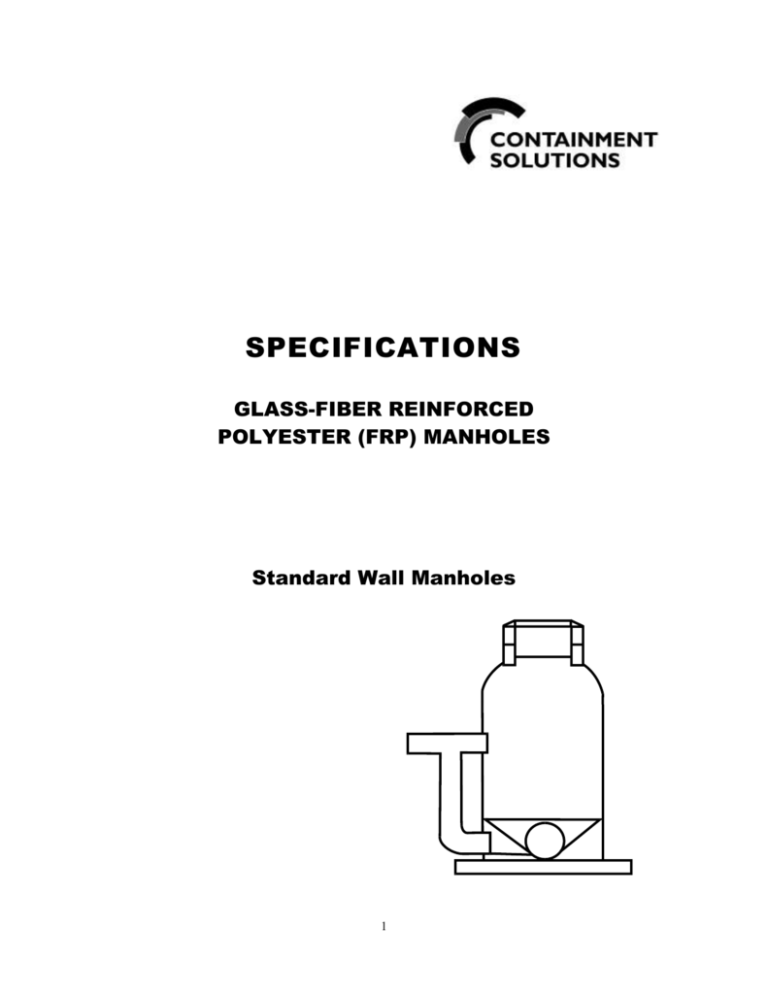
Standard Wall Manholes
1
SPECIFICATIONS
GLASS-FIBER REINFORCED POLYESTER (FRP) MANHOLES
I.
SCOPE OF WORK
This specification shall govern for the furnishing of all work necessary to accomplish and complete the installation of
glass-fiber reinforced polyester manholes. Glass-Fiber Reinforced Polyester Manholes shall be a one-piece
monolithic designed unit constructed of glass-fiber reinforced, supplier certified, unsaturated commercial
grade polyester resin containing chemically enhanced silica to improve corrosion resistance, strength and
overall performance. FRP manholes shall be manufactured in strict accordance with ASTM D-3753 “Standard
Specification for Glass-Fiber Reinforced Polyester Manholes”, as manufactured by Containment Solutions, Inc.,
Conroe, Texas, Fiberglass manholes, or Engineer Pre-Approved Equal.
II. GOVERNING STANDARDS
Manholes shall conform to the following design criteria:
A. ASTM D-3753: Standard Specification for Glass-Fiber Reinforced Polyester Manholes.
B. ASTM C-581:
Practice for Determining Chemical Resistance of Chemical
Thermosetting Resins Used in Glass-Fiber Reinforced Structures
Intended for Liquid Service.
C. ASTM D-2412: Test Method for Determination of External Loading Characteristics of
Plastic Pipe by Parallel Plate Loading.
D. ASTM D-695:
Test Methods for Compressive Properties of Rigid Plastics.
E. ASTM D-2584: Test Method for Ignition Loss of Cured Reinforced Resins.
F. ASTM D-790:
Test Method for Flexural Properties of Unreinforced and Reinforced
Plastics and electrical Insulating Materials.
G. ASTM D-2583: Test Method for Indentation Hardness of Rigid Plastics by means of a
Barcol Impressor.
H. AASHTO H-20: Axle Loading.
III. GENERAL DESCRIPTION
A. Dimensions: The manhole shall be a circular cylinder, reduced at the top to a circular manway not smaller
than 22 1/2” inside diameter. Manholes shall be produced in half-foot increments in length +/- 2”. Nominal
inside diameters shall be 42“, 48”, 54”, 60”, 66”, and 72“. Tolerance on the inside diameter shall be +/- 1%.
Other diameters as agreed upon between purchaser and the manufacturer are covered by this
specification.
B. Configuration:
1). Cone Sections:
The Manway reducer must provide a bearing surface on which a standard ring and cover may be supported
and adjusted to grade. The reducer shall be concentric and shall be joined to the barrel section at the
factory with resin and glass fiber reinforcement, thus providing required monolithic design to prevent
infiltration and/or exfiltration through the manhole.
Manway reducer cone section shall be self-centering to permit vertical height adjustment (raising
2
or lowering) of manhole by contractor utilizing manufacturer provided materials and detailed written
instructions.
C. Class: The manhole shall be manufactured in one class of load rating. This class shall be H-20 wheel load
(minimum 16,000 pounds dynamic wheel load).
D. Stubouts and Connections:
1). Inserta-Tee: Joints for sewer pipe line and drop connections sizes 4” - 12” shall be made by means of
Inserta-Tee watertight compression connection. Installation shall be in strict accordance with manufacturer’s
written instructions utilizing installation equipment approved for use by the manufacturer of the Inserta-Tee
fitting. Use of equipment which does not meet this requirement is expressly prohibited.
2). Pipe Stubouts:
a. Install PVC sewer plain end pipe stubouts to manhole with resin and glass-fiber reinforced lay-up.
Belled fittings (if required) shall meet the same performance requirements of the sewer pipe to be
installed unless otherwise directed by the Engineer. Resin and fiberglass shall be of the same type
and grade as used in the fabrication of the fiberglass manhole.
b. Install pipe-to-manhole connectors (boots) which conform to the performance requirements of ASTM
C-923.
E. Manhole Bottom: Resin and glass fiber reinforced manhole bottoms may be provided, upon engineer’s
request. Upon that request, manholes shall be provided with glass reinforced bottom section designed to
withstand the hydrostatic head pressure, empty and water to grade, 25-ft. burial depth.
(Units deeper than 25-ft. may require additional reinforcement as required). Fiberglass ribs or fiberglass
structural members may be utilized to meet the design criteria. Stiffeners shall be of non-corrosive materials
encapsulated in fiberglass. FRP encapsulated wood or lumber will not be permitted. Bottom sections shall
be furnished with an integral 3” wide anchoring flange. Invert and bench may be field installed utilizing
concrete to the requirements of Division 3. Invert and bench may be factory installed utilizing non-corrosive
materials encapsulated in fiberglass minimum 1/4” thick.
F. Marking and Identification: All manholes shall be marked with the following information:
1)
2)
3)
4)
Manufacturers Identification
Manhole Length
ASTM Designation
Installation assist marks (vertical lines 900 apart at base of manhole).
IV. MATERIALS
A. Resin: The resins used shall be unsaturated, supplier certified, commercial grade polyester resins. Mixing
lots of resin from different manufacturers, or “odd-lotting” of resins shall not be permitted. Qualityassurance records on the resin shall be maintained. Non-pigmented Resin is required to allow for light or
“sand” color of manhole surface in order to facilitate easy from grade interior inspection. UV Inhibitors
shall be added directly to resins to prevent photodegradation.
B. Reinforcing Materials: The reinforcing materials shall be commercial grade “E” type glass in the form of
mat, continuous roving, chopped roving, roving fabric, or both, having a coupling agent that will provide a
suitable bond between the glass reinforcement and the resin.
C. Surfacing Material: If reinforcing material is used on the surface exposed to the contained substance, it
shall be a commercial grade chemical-resistant glass or organic surfacing mat having a coupling agent that
will provide a suitable bond with the resin.
3
D. Fillers and Additives: Fillers, when used, shall be inert to the environment and manhole construction.
Additives, such as thixotropic agents, catalysts, promoters, etc., may be added as required by the specific
manufacturing process to be used to meet the requirements of this standard. However, calcium carbonate
mixed by the fabricator shall not be permitted. The resulting reinforced plastic material must meet the
requirement of this specification.
E. Laminate: The laminate shall consist of multiple layers of glass matting and resin. The surface exposed to
the sewer/chemical environment shall be resin rich and shall have no exposed fibers.
V. MANUFACTURE
A. Manhole cylinders, manway reducers, and connectors shall be produced from glass fiber-reinforced
polyester resin. Manhole cylinders to 72” ID to be manufactured by “computer regulated mandrel process”,
72” ID and larger to be manufactured by computer regulated steel mandrel process utilizing structural rib
design.
B. Interior Access: All manholes shall be designed so that a ladder or step system can be supported by the
installed manhole. Manway openings to accommodate 24” or 32” standard ring and cover.
C. Manway Reducer: Manway reducers shall be concentric with respect to the larger portion of the manhole
diameters through 72”.
D. Cover Ring and Support: The manhole shall provide an area from which a typical ring and cover plate can
be supported without damage to the manhole.
E. Assembly Joints: Product components, i.e., cylinders, reducers, bottoms, and connectors, may be joined
together to form a complete manhole.
VI. REQUIREMENTS
A. Exterior Surface: The exterior surface shall be relatively smooth with no sharp projections. Hand-work
finish is acceptable if enough resin is present to eliminate fiber show. The exterior surface shall be free of
blisters larger than 0.5” in diameter, delamination and fiber show. Gel-coat or paint or other coatings are
not allowed.
B. Interior Surface: The interior surfaces shall be resin rich with no exposed fibers. Interior surface shall be
smooth for improved corrosion resistance and reduced sludge build-up. The surface shall be free of
crazing, delamination, blisters larger than 0.5” in diameter, and wrinkles of 0.125” or greater in depth.
Surface pits shall be permitted up to 6/ft2 if they are less than 0.75” in diameter and less than 0.0625” deep.
Voids that cannot be broken with finger pressure and that are entirely below the resin surface shall be
permitted up to 4/ft2 if they are less than 0.5” in diameter and less than 0.0625” thick. Gel-coat or paint or
other coatings are not allowed.
C. Repairs: Any manhole repair is required to meet all requirements of this specification.
D. Manhole Lengths: Manhole lengths shall be in whole or 1/2-foot increments +/- 2”.
E. Load Rating: The complete manhole shall have a minimum dynamic load rating of 16,000 lbs. when tested
in accordance with ASTM 3753, 8.4 (note 1). To establish this rating the complete manhole shall not leak,
crack, or suffer other damage when load tested to 40,000 lbs. and shall not deflect vertically downward
more than 0.25” at the point of load application when loaded to 24,000 lb.
4
F. Stiffness: The cylindrical portion of the manhole is to be tested in accordance with ASTM Method D 2412.
The manhole cylinder shall have the minimum pipe-stiffness values shown in the table below, when tested
in accordance with ASTM 3753, Section 8.5, (note 1).
Manhole Length (ft)
PSI
3-6
0.72
7 - 12
1.26
3 - 20
2.01
21 - 25
3.02
26 - 35
5.24
G. Soundness: In order to determine soundness, an air or water test is to be applied to the manhole test
sample. While holding the pressure between 3-5 psi, the entire manhole must be inspected for leaks. Any
leakage through the laminate is cause for failure of the test. Refer to ASTM 3753, Sec. 8.6.
H. Chemical Resistance: Per ASTM C 581; (see ASTM 3753, Section 8.7), Flexural strength, flexural
modulus, and barcol hardness are plotted versus time on log-log coordinates. The line defined by these
points is extrapolated to 100,000 hours. The minimum extrapolation retention allowed for any of these
properties is 50%. Test samples used are actual pieces of manhole or samples manufactured in a manner
consistent in every way with the manhole component construction.
I.
Physical Properties:
Flexural Strength (cone):
Flexural Strength (pipe)
Hoop:
Axial:
Hoop:
Axial:
Compressive Strength:
15.4 x 10³ psi
17.2 x 10³ psi
22.5 x 10³ psi
14.3 x 10³ psi
8.9 x 10³ psi
VII. TEST METHODS
A. All tests shall be performed as specified in ASTM 3753, Section 8, Titled “Test Methods”. See ASTM 3753,
Section 8, Note 5, for Test method D-790 and test method D-695.
VIII. QUALITY ASSURANCE/QUALITY CONTROL
A. Examination: Each manhole component part shall be examined for dimensional requirements, hardness,
and workmanship.
B. Composition Control: Controls on glass and resin content shall be maintained for all manufacturing
processes and for each portion of manhole fabrication. Records shall be maintained for these control
checks. Proper glass content may be shown by glass usage checks or glass and resin application rate
checks, in accordance with the material composition test in ASTM 8.8.1.
C. All required ASTM 3753 testing shall be completed and records of all testing shall be kept and copies of test
results shall be presented to customer upon written request within a reasonable time period.
5
IX. CERTIFICATION
A. When requested by the purchaser on his order, a certification shall be made the basis of acceptance. This
shall consist of a copy of the manufacturer’s test report or a statement by the supplier, accompanied by a
copy of the test results, that the manhole has been sampled, tested, and inspected in accordance with the
provisions of ASTM 3753 and this specification, and meets all requirements. An authorized agent of the
supplier or manufacturer shall sign each certification so furnished.
X. HANDLING AND STORAGE
A. Do not drop or impact the fiberglass manhole. Lift manhole with two slings on spreader bar in horizontal
position or an appropriately sized timer or steel beam, 8” longer than the cone top opening, inserted
crosswise inside the manhole to the underside of the collar with a rope or chain attached to backhoe or
other lifting device. Manhole may be rolled, however, insure that ground is smooth and free of rocks, debris,
etc. Use of chains or cables in contact with manhole surface is prohibited.
XI. INSTALLATION METHODS
A. General: The manhole installation should strictly follow the manufacturers recommended installation
procedures.
1. To Install The Fiberglass Manhole: Fiberglass manholes must be installed according to Containment
Solution’s Fiberglass Manhole Installation Instructions”.
In addition to these instructions, local codes may apply and should be consulted as applicable in
manhole installation. Correct manhole installation requires proper concrete foundation, good backfill
and proper handling to prevent manhole damage and insure long-term corrosion resistant service.
B. General Installation Outline: Containment Solution’s complete Manhole installation instructions must be
consulted before actual installation is performed.
1. Prepare Excavation/Make Manhole Pipe Cut-Outs for stubout connections: Prepare excavation in a
normal manner. Excavation at manhole location should be at least wide enough to accommodate the
slab specified and to provide working room around manhole. Insure the depth of manhole is sufficient to
allow at least one course of brick or one concrete ring for adjustment of ring and cover at top of final
grade. Pipe cut-outs at the flowline are made in manhole prior to setting manhole in place over pipe in
trench. Quarter marks have been provided on barrel to facilitate alignment of cut-outs.
2. Pour Concrete Base: Concrete slab base should be a minimum of 6” thick for up to 48” diameter
manholes (8” for larger diameter manholes). Concrete slab should extend a minimum of 12” beyond
manhole outside wall for manholes up to 20’ in depth (24” up to 35’ in depth).
3. Set Manhole: To lift manhole, insert an appropriately sized timber or steel beam, 8” longer than the cone
top opening, crosswise inside the manhole to the underside of the collar with a rope or chain attached to
backhoe or other lifting device. Lower manhole into wet concrete base to a minimum depth of 4”.
Minimum 2” thick concrete bearing surface beneath bottom edge of the manhole is required. Plumb
manhole using standard bubble level and by moving manhole with hands. Work concrete around
manhole base and 6 inch minimum over incoming lines. Inverts and laterals are made following standard
procedures.
6
4. Backfill: Backfilling is done just as soon as the concrete base has hardened enough to provide sufficient
support for manhole and fill. Native soil ( or sand, in unstable areas), free of large stones, debris, or
concrete chunks may be used for backfill. Backfill should be place evenly around manhole in 12”
maximum lifts and should thoroughly tamped to 90% standard proctor density before the next layer is
installed. Backfill material shall be subject to approval by the engineer.
5. Bring to Grade: Construct chimney on flat shoulder of manhole using precast concrete rings.
XII. INSPECTION
A. The quality of all materials, the process of manufacture, and the finished sections shall be subject to
inspection and approval by the Engineer, or other representative of the owner. Such inspections shall be
made at the place of manufacture, or at site of delivery, and the sections shall be subject to rejection on
account of failure to meet any of the specification requirements. Sections rejected after delivery to the job
site shall be marked for identification and shall be removed from the job at once. All sections which have
been damaged after delivery will be rejected, and if already installed shall be acceptable if repaired or
removed and replaced at the contractor’s expense.
B. At the time of inspection the material will be examined for compliance with the requirements of this
specification and the approved drawings.
XIII. MEASUREMENT
This item will be measured will be measured by each type of individual structure completed. The depth will be
measured from the flow line to the top of the rim. The size shall be nominal inside diameter. This item
includes, but is not limited to the following:
A. Structural excavation
B. Loading, hauling, and disposing of all excess material
C. Furnishing all labor and materials including fiberglass, concrete, mortar, bricks, drop pipe and fittings,
manhole rings and covers
D. Placing and compacting all backfill
E. Final Grading
XIV.
PAYMENT
A. This item will be paid for at the contract unit price per bid per each structure for the various sizes, types, and
various depths of structures complete in place and will be full compensation for all materials required,
operations, labor, tools, equipment, and all other incidentals necessary to complete the work as shown on
the drawings and specified herein.
Litho in U.S.A., July 2010 Copyright 2010 Containment Solutions, Inc. - All Rights Reserved Pub. No. MAN 4040A
7

