Laser based Telecommunications
advertisement

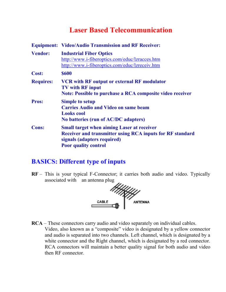
Laser Based Telecommunication Equipment: Video/Audio Transmission and RF Receiver: Vendor: Industrial Fiber Optics http://www.i-fiberoptics.com/educ/lzracces.htm http://www.i-fiberoptics.com/educ/lzreceiv.htm Cost: $600 Requires: VCR with RF output or external RF modulator TV with RF input Note: Possible to purchase a RCA composite video receiver Pros: Simple to setup Carries Audio and Video on same beam Looks cool No batteries (run of AC/DC adapters) Cons: Small target when aiming Laser at receiver Receiver and transmitter using RCA inputs for RF standard signals (adapters required) Poor quality control BASICS: Different type of inputs RF – This is your typical F-Connector; it carries both audio and video. Typically associated with an antenna plug RCA – These connectors carry audio and video separately on individual cables. Video, also known as a “composite” video is designated by a yellow connector and audio is separated into two channels. Left channel, which is designated by a white connector and the Right channel, which is designated by a red connector. RCA connectors will maintain a better quality signal for both audio and video then RF connector. Composite-video cable S-Video – “S” is short for Super. This video connector separates the luminance (brightness) and chrominance (color) information over 4 individual wires within the cable. It only carries video information, but it provides a better quality signal. S-Video cable Component Video - Component video improves the picture quality even more by not only separating the color from the black-and-white portions of the picture but by further splitting the color information into two color-difference signals. When the picture signal is split up in this way, you get an unfiltered, uninterrupted image, with better resolution and greatly improved color saturation. Component-video cable Laser Telecommunications History The use of light in communication is by no means a 20 th century concept. In fact, in 1880, Alexander Graham Bell patented the photophone. However, it is the telephone that made him famous, not the photophone. One reason why the photophone was not as successful as the telephone was that the technology to efficiently send light from one point to another did not exist at the time. Light from ordinary sources follows the inverse square rule. When the distance between a light source and an object is doubled, the intensity of the light shining on the object becomes one-fourth of what it was. This is the reason why the technology to send light from one point to another was very inefficient. Whereas light from other sources spreads out, light from a laser is extremely directional. With the invention of the laser, the ability to efficiently send light from one point to another became a reality. The potential for transferring information using lasers was great. Here we present a communications kit that demonstrates the basic concepts behind a modern telecommunications system. Operational description of the Industrial Fiber Optics Laser Audio Transmission Project and RF Receiver Mainly, there are two parts in this telecommunications kit: the transmitter and the receiver. The transmitter has a RF input that is implemented with a standard RCA jack. The receiver is connected to the television and has a RF output that uses standard RCA jack. The maximum analog voltage input that the laser can handle without distortion is 50 millivolts peak-to-peak. The frequency range of the modulated signal has to be within the range of 100 Hz to 70 MHz. Due to a wide range of frequencies - WBS laser can be used with a wide variety of sources that transfer audio, video or audio/video signals. Examples of compatible signal sources include dynamic microphones, video outputs from television or VCR’s (when used with an attenuator), and modulated RF signals from VCR’s or external modulator boxes. When such sources are being used along with the WBS laser, one must make sure that their output doesn’t exceed 50 mV peak-to-peak. Operations with microphone The microphone (mic) normally use standard 3.5 mm (1/4 inch) or 6.3 mm (1/8 inch) plugs. In order to connect it to the WBS laser (analog input labeled “VID”) 3.5/6.3 mm RCA male adapters must be used. In the case when the microphone has XLR plug, the special XLR RCA male adapter must be purchased. When the system is operating, the microphone picks up sound (an audio signal) and converts it into an analog electrical signal, a signal in which the EMF changes with time. When the signal’s voltage increases, the intensity of light from the laser increases. When the signal’s voltage decreases, the intensity of the laser light decreases. To put it simply, the transmitter converts a sound signal into an optical signal; a signal in which the intensity of light outputted varies with time. This optical signal travels in the direction the laser is pointed, and when the laser is pointed at the photodiode in the receiver, the photodiode converts the laser light signal into an electric signal (a voltage). When the intensity of the laser beam is high, the photodiode produces more voltage than when the intensity of the laser beam is low. And so it follows that the photodiode in the receiver converts the optical signal back into an electrical signal. This electrical signal is then amplified, and then is sent out to the speaker in the television, where the signal is finally converted back to sound. And provided there is little noise in the entire system, the sound should be the same as the sound that was picked up by the microphone. Operations with Audio, Video or Audio/Video sources In addition to transferring sound, the communications system transfers video. A camcorder, CD-player, DVD player or other device that outputs an audio/video signal is connected to an external modulator (RF modulator). The modulator takes low frequency audio, video or audio/video signals to convert them to a higher radio frequency modulated signal. The output of the modulator can be connected by 75-Ohm “F” type coaxial cable (coax cable) to the WBS laser transmitter. Note: “F” type to RCA type adapter has to be attached (F-> RCA)) to the cable on the transmitter end. The laser then creates an optical signal. The optical signal is sent to the receiver, where it is converted back into an electrical audio/video signal, which is sent to the television RF demodulator that converts it into an image and/or a sound. Operations with VCR As described in the section above, WBS can be used to transfer combination of both audio/video signals. Since the VCR’s have a built in RF modulator, there is no need to use an external RF modulator. The “F” type of output of the VCR can be connected with the 75-Ohm coaxial cable (coax cable) to the WBS laser transmitter. Note: “F” type to RCA type adapter has to be attached to the cable on the transmitter end. The VCR output as well as TV input has to be set to channel 3 or 4. VCR can be connected in many different ways with the given setup. For instance, in case when the professional type of monitor is being used (only has RF or S-video input), VCR can work as demodulator. The output of the receiver can be connected to the VCR through coaxial cable to the VCR’s antenna input. The VCR RCA/S-video output can be connected to the monitor RCA/S-video input. Also, a spare VCR can be often used as an external RF modulator with a little caution: if you connect the DVD or DVD-Rom through your VCR you can get Macrosplat. The brightness will constantly fade in and out due to the Macrovision copyright protection on the DVD. To kill Macrosplat you can use Sima Video CopyMaster (CopyMaster). Note: the laws strictly prohibit unauthorized copy of some video material. Possible problems and causes associated with them One of the problems that user of the laser telecommunication package can face with is overdriven input. To avoid this problem one have to make sure that the maximum amplitude of an input signal doesn’t exceed 50 mV. In the case when the input voltage is over 50 mV a signal attenuator should be used to decrease the input voltage. One of the possible causes for not getting a stable reception is an interference caused by the AC line. In such a case user must use high quality AC line enhancers to overcome this problem. Another option is to connect to a different AC line or perform experiment in a different place where AC line doesn’t cause interference problems. Conclusion Although Industrial Fiber Optics Laser Audio Transmission Project and RF Receiver are similar to modern telecommunications systems used today, in many ways they differ. For example, with the way the communications system works, the farther the transmitter and receiver are, the more difficult it is to line up the laser beam. Also, when the distance between the transmitter and receiver is large, there are more obstacles get in the path of the beam. It is possible to get past many obstacles by using an elaborate system of mirrors, however, it is by no means practical for long distance communications and when the weather changes, fog and precipitation makes laser communication using the atmosphere as a medium nearly impossible. To overcome that obstacle, fiber optics is used as the medium through which light travels (a project that we plan to implement as part of this community service program). Also, in a modern communications system, the signal is digital, not analog. Starting 2006 all of the terrestrial broadcast will be done in HDTV (High Definition Television) format that provides incredible picture clarity. The clarity of the picture is due to high picture resolution that requires a huge bandwidth. The bandwidth of the current RG-6 coaxial cable used now days by the cable companies is not wide enough to carry sufficient amount of HDTV broadcast. In a near future we will see dramatic changes that will happen with cable company distribution networks. An RG-6 cable is going to be replaced with a fiber-optic cable that has much higher bandwidth. Television will become more interactive. The larger amount of TV channels will be provided. The sound quality will get even better. For instance, Dolby Digital is an adopted format for HDTV broadcast that provides 5.1-channel surround sound. But the wide bandwidth of the fiber-optic line isn’t the only advantage over the conventional coaxial line. In our era of radio communication there is a huge air traffic that causes a lot of interferences in regular copper network lines. Fiber-optic line isn’t affected by such interferences and can easily withstand powerful electromagnetic impulses. Therefore more and more often we are going to see fiber-optic lines replacing copper wire lines. List of adapters that can be useful S-video male RCA female (S-video -> RCA) can be used to connect video sources that only have S-video output to a VCR or an external RF modulator (example: Laptop computer, most of the desktop computer video cards only offer an S-video output). RF female RCA male adapter (F->RCA) have to be used to connect laser transmitter and receiver to standard “F” type coaxial 75-Ohm cables. XLR male RCA male adapter (XLR-RCA) can be used to connect XLR terminated microphone. 3.5 mm RCA male adapter (3.5mm->RCA) can be used to connect microphone terminated with the mini plug (1/8 inch) 6.3 mm male RCA male adapter (6.3mm->RCA) can be used to connect microphone terminated with ¼ inch plug Note: to preserve the highest quality of a signal use only the high quality cables along with the high quality adapters. Try to use a minimum amount of adaptors as well. The following adaptors can be used in the case when certain adaptors are not accessible: 3.5 mm (1/4”) 6.3 mm (1/8”) adapter (3.5->6.3 mm) to use when 3.5 mm RCA male isn’t available 6.3 mm (1/4”) 3.5 mm (1/8”) adapter (6.3->3.5 mm) to use when 6.3 mm RCA male adapter isn’t available


