Sphere Research Corporation
3394 Sunnyside Rd., Kelowna, B.C. V1Z 2V4
CANADA
Contact information:
Sphere Research Corporation
Technical Bulletin
Using Tektronix Lab Scopes
Phone: (250) 769-1834
FAX:
(250) 769-4106
E-Mail: walter2@sphere.bc.ca
URL:
http://www.sphere.bc.ca
Important Information !
Rev. 2.2
Thanks for buying a reconditioned Tektronix scope from Sphere Research!
To help you get the best value from your scope, and keep it in top condition, here are a few important
operating and equipment pointers from us:
1. Many people hunt a long time for the odd power switch, and once they find it (on the front, usually by the
CRT), can’t figure out how to turn it on. If it’s a rounded gray bulb, IT PULLS OUT to turn the scope on.
2. Using 50 ohm coax to connect RF to the scope is fine, but keep in mind, into a 1M input, it produces a
severe low pass filter, and rolls off by about 11 Mhz, ruining the wide bandwidth of your expensive scope.
Use a 50 ohm feed through terminator at the scope input if you intend to use 50 ohm coax (the input Z
will now be 50 ohms), and all will be fine.
3. Many vertical plug ins like the 7A26 have a reduced bandwidth switch, usually with positions marked
20Mhz, and FULL. Be careful about the setting of this switch, as it will make high frequencies (and
sharp rising edges) disappear when in the lower bandpass setting. The reduced bandwidth is meant to be
used with low frequency signals that have RF noise present thanks to exposed interconnect, or long leads,
and using less bandwidth allows the signal to be observed easier.
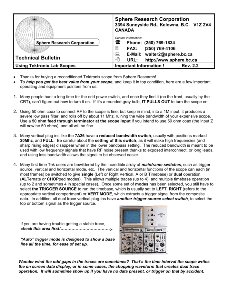
4. Many first time Tek users are bewildered by the incredible array of mainframe switches, such as trigger
source, vertical and horizontal mode, etc. The vertical and horizontal functions of the scope can each (in
most frames) be switched to give single (Left or Right Vertical, A or B Timebase) or dual operation
(ALTernate or CHOPped modes). This allows multiple traces (up to 4), and multiple timebase operation
(up to 2 and sometimes 4 in special cases). Once some set of modes has been selected, you still have to
select the TRIGGER SOURCE to run the timebase, which is usually set to LEFT, RIGHT (refers to the
appropriate vertical compartment) or VERT MODE, which extracts a trigger signal from the composite
data. In addition, all dual trace vertical plug-ins have another trigger source select switch, to select the
top or bottom signal as the trigger source.
If you are having trouble getting a stable trace,
check this area first!………………………………>
“Auto” trigger mode is designed to show a base
line all the time, for ease of set up.
Wonder what the odd gaps in the traces are sometimes? That’s the time interval the scope writes
the on screen data display, or in some cases, the chopping waveform that creates dual trace
operation. It will sometime show up if you have no data present, or trigger on that by accident.
5. There are also more intensity controls than most people are used to. In larger frames, there are both
READOUT (the data display on the top and bottom of the screen) and INTENSITY (trace) controls, PLUS,
in 4 slot frames, there are A and B intensity controls, which permit each timebase to have independent
intensity control.
6. The built in calibrator is used to quickly confirm vertical calibration (all Tek vertical plug ins can be
calibrated from the front panel), and to set probe compensation. A clean square wave should be
displayed (at approx. 1Khz), with clean leading and trailing edges. If the waveform is rounded or
differentiated, adjust the probe compensation capacitor (refers to 10X probes only) for a clean square
wave before attempting any measurements. Mis-adjusted probes can be wildly inaccurate.
7. Vertical plug ins have an input coupling switch (AC/GND/DC) that allows control over the type of input
connection to the signal under test. AC will couple via a capacitor (ideal for removing a large DC bias to
see a small AC signal) and has some loss of low frequency information (square wave tilt) as a result. DC
is a direct connection, and extends bandwidth down to DC, GND shorts the amplifier input (not the signal!)
to ground, to let you establish a zero reference on screen.
<……………A common problem?
The input selector gets knocked by accident into
the center GND position while attaching a
probe, so no signal appears on the screen as a
result
8. The timebase usually has both 1X and 10X multipliers. The 10X multiplier expands the screen scan
10 times, allowing examination of fine detail on the wave train, but reduces intensity in proportion as a
result. Trace seem a bit dim, and position behaving oddly? You may be in the 10X mode by accident.
9. Trigger selection is a hard concept for many people to keep straight. The timebase has to first GET a
trigger signal from somewhere to start the sweep, this is set partially on the scope mainframe, and
sometimes on the vertical plug in. In addition, the COUPLING of the trigger (AC, DC, LF, HF LINE) and
its LEVEL must be set. Tek scopes also have an AUTO mode, which always displays a trace (very
handy), but still allows the trigger threshold to be set. Why have a trigger? It is impossible to obtain a
stable display (especially at high speeds) unless the sweep is synchronized to the source, so that the trace
begins at the same point each scan, allowing you to resolve detail and improve intensity.
10. The on screen data display shows the current scale factors the scope is operating under. If you are
using correct indicating style Tek probes (or the generic equivalent), a 10X probe will be factored into the
display, and give the corrected scale factor. The 1X /10X sweep magnifier is handled the same way, and
always shows the true scale factor on the screen. When the VARIABLE adjustment for any channel is out
of its detent (calibrated) position, the display shows “>” in front of the scale factor (such as >10mV), to
advise the signal is now greater than the indicated factor. If inversion is selected on a vertical plug in, a
small downward arrow “” will appear in front of the scale factor indicating positive deflection is now
downwards.
11. In theory, all plugins work in all slots, in practice this is not completely true. While any timebase can be
used in any frame, there is often a notation on the frame slot, indicating the maximum calibrated sweep
speed possible (e.g., 10ns). Putting a faster timebase or wider bandwidth vertical amplifier in does not
alter the limitations of the mainframe, and putting in a slower plug in will reduce the mainframe
performance to that of the plug in.
7000 series Frames are in several distinct groups:
7403 frames are 60Mhz
7503, 7514 & 7504 frames are 90Mhz
7603, 7613, 7623, 7633 frames are 100Mhz
7704, 7704A frames are 200Mhz
7834, 7844, 7854 frames are 400Mhz
7903 & 7904 frames are 500Mhz
7104 frames are 1Ghz
Plug ins are grouped as follows (maximum performance shown):
Timebases:
7B5x to 100Mhz
7B7x to 200Mhz
7B8x to 400Mhz
7B9x to 500Mhz
7B1x to 1Ghz.
Vertical Amplifiers:
7A11 to 200Mhz (w/built in probe)
7A15/A, 7A18A to 80/75Mhz
7A16/A, 7A26 to 225/200Mhz
7A24 to 400Mhz
7A19 to 600Mhz
7A29 to 1Ghz
Turn the POWER OFF when installing or removing a plug in. Turn the intensity down, or the scope off
when not in use to preserve the CRT life (the most expensive part of the scope!). Extended high
intensity will damage storage scopes quickly, and regular scopes over time. Be careful!
Things that can be altered after SHIPPING or moving modules!
Trace blurry? Adjust focus or astigmatism control (may be trim adjust on some scopes).
Trace look crooked? Adjust the trace rotation pot for the straightest trace, on the back on 5000 series.
Can’t see the on-screen scale factors? They have their own intensity control, be sure it’s set right.
Plug in gain or time slightly off? Adjust front panel cal trimpot or hidden “variable” feature for correct
scaling (use a known good source!).
Tek scopes and logic analyzers run HOT to get fast speed/wide bandwidth, so do
not block the vents or cover up any piece of equipment or it may fail
prematurely.
This is very important, but easy to forget.
Contents copyright 1999, 2001, 2003 by Sphere Research Corporation, all rights reserved


