Section 8. ACOUSTIC EMISSION
advertisement
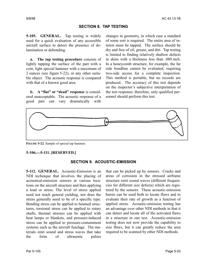
9/8/98 AC 43.13-1B SECTION 8. TAP TESTING 5-105. GENERAL. Tap testing is widely used for a quick evaluation of any accessible aircraft surface to detect the presence of delamination or debonding. a. The tap testing procedure consists of lightly tapping the surface of the part with a coin, light special hammer with a maximum of 2 ounces (see figure 5-22), or any other suitable object. The acoustic response is compared with that of a known good area. b. A “flat” or “dead” response is considered unacceptable. The acoustic response of a good part can vary dramatically with changes in geometry, in which case a standard of some sort is required. The entire area of interest must be tapped. The surface should be dry and free of oil, grease, and dirt. Tap testing is limited to finding relatively shallow defects in skins with a thickness less than .080 inch. In a honeycomb structure, for example, the far side bondline cannot be evaluated, requiring two-side access for a complete inspection. This method is portable, but no records are produced. The accuracy of this test depends on the inspector’s subjective interpretation of the test response; therefore, only qualified personnel should perform this test. FIGURE 5-22. Sample of special tap hammer. 5-106.5-111. [RESERVED.] SECTION 9. ACOUSTIC-EMISSION 5-112. GENERAL. Acoustic-Emission is an NDI technique that involves the placing of acoustical-emission sensors at various locations on the aircraft structure and then applying a load or stress. The level of stress applied need not reach general yielding, nor does the stress generally need to be of a specific type. Bending stress can be applied to beamed structures, torsional stress can be applied to rotary shafts, thermal stresses can be applied with heat lamps or blankets, and pressure-induced stress can be applied to pressure-containment systems such as the aircraft fuselage. The materials emit sound and stress waves that take the form of ultrasonic pulses Par 5-105 that can be picked up by sensors. Cracks and areas of corrosion in the stressed airframe structure emit sound waves (different frequencies for different size defects) which are registered by the sensors. These acoustic-emission bursts can be used both to locate flaws and to evaluate their rate of growth as a function of applied stress. Acoustic-emission testing has an advantage over other NDI methods in that it can detect and locate all of the activated flaws in a structure in one test. Acoustic-emission testing does not now provide the capability to size flaws, but it can greatly reduce the area required to be scanned by other NDI methods. Page 5-53 AC 43.13-1B 9/8/98 5-113. APPLICATIONS. A wide variety of structures and materials, such as: wood, plastic, fiberglass, and metals can be inspected by the acoustic-emission technique by applying stress on the test material. The emission-producing mechanism in each type of material may differ, but characteristic acoustic-emissions are produced and can be correlated to the integrity of the material. Acoustic-emission technology has been applied quite successfully in monitoring proof tests of pressure vessels and tests of fiber-reinforced plastic structures of all kinds. There are now ASTM standards and ASME codes applying to its use in testing gas cylinders and both metal and fiber-reinforced plastic vessels, tanks, and piping. For a welded structure such as a pressure vessel, acoustic-emission testing works well with relatively simple instrumentation. However, slight movement of bolted or riveted joints can also generate acoustic signals. Thus a complex structure may have many acoustic sources besides flaws in its components. These unwanted emission sources greatly complicate acoustic-emission tests of complex structures. The difficulties are not prohibitive, but they put a premium on the intelligent use of signal processing and interpretation. Therefore, because of the complexity of aircraft structures, application of acoustic-emission testing to aircraft has required a new level of sophistication, both in testing techniques and data interpretation. Research and testing programs are currently in progress to determine the feasibility of acoustic-emission testing on several different types of aircraft. 5-114.5-119. [RESERVED.] SECTION 10. THERMOGRAPHY 5-120. GENERAL. Thermography is an NDI technique that uses radiant electromagnetic thermal energy to detect flaws. The presence of a flaw is indicated by an abnormal temperature variant when the item is subjected to normal heating and cooling conditions inherent to the in-service life, and/or when artificially heated or cooled. The greater the material’s resistance to heat flow, the more readily the flow can be identified due to temperature differences caused by the flaw. 5-121.5-126. [RESERVED.] SECTION 11. HOLOGRAPHY 5-127. GENERAL. Holography is an NDI technique that uses visible light waves coupled with photographic equipment to create a three-dimensional image. The process uses two laser beams, one called a reference beam and the other called an object beam. The two laser beams are directed to an object, between beam applications the component is stressed. The beams are then compared and recorded Page 5-54 on film, or other electronic recording medium, creating a double image. Indications of applied stresses or defects are shown as virtual images with a system of fringe lines overlaying the part. Holography is most commonly used for rapid assessment of surface flaws in composite structures. 5-128.5-133. [RESERVED.] Par 5-113 9/8/98 AC 43.13-1B SECTION 12. SHEAROGRAPHY 5-134. GENERAL. Shearography was developed for strain measurements. The process now provides a full-field video strain gauge, in real time, over large areas. It is an enhanced form of holography, which requires the part to be under stress. A laser is used for illumination of the part while under stress. The output takes the form of an image processed video display. This technique has been used effectively in locating defects, such as disbonds and delaminations, through multiple bondlines. It is capable of showing the size and shape of subsurface anomalies when the Par 5-134 test part is properly stressed. Shearography has been developed into a useful tool for NDI. It can be used easily in a hangar environment, while meeting all laser safety concerns. Other applications include the testing of honeycomb structures, such as flaps and control surfaces. Shearography offers a great increase in the speed of inspection by allowing on-aircraft inspections of structures without their removal, as well as inspections of large areas in just seconds. 5-135.5-140. [RESERVED.] Page 5-55 (and 5-56)

