Example Sequence of Operation Test form for a Chilled Water System:
advertisement
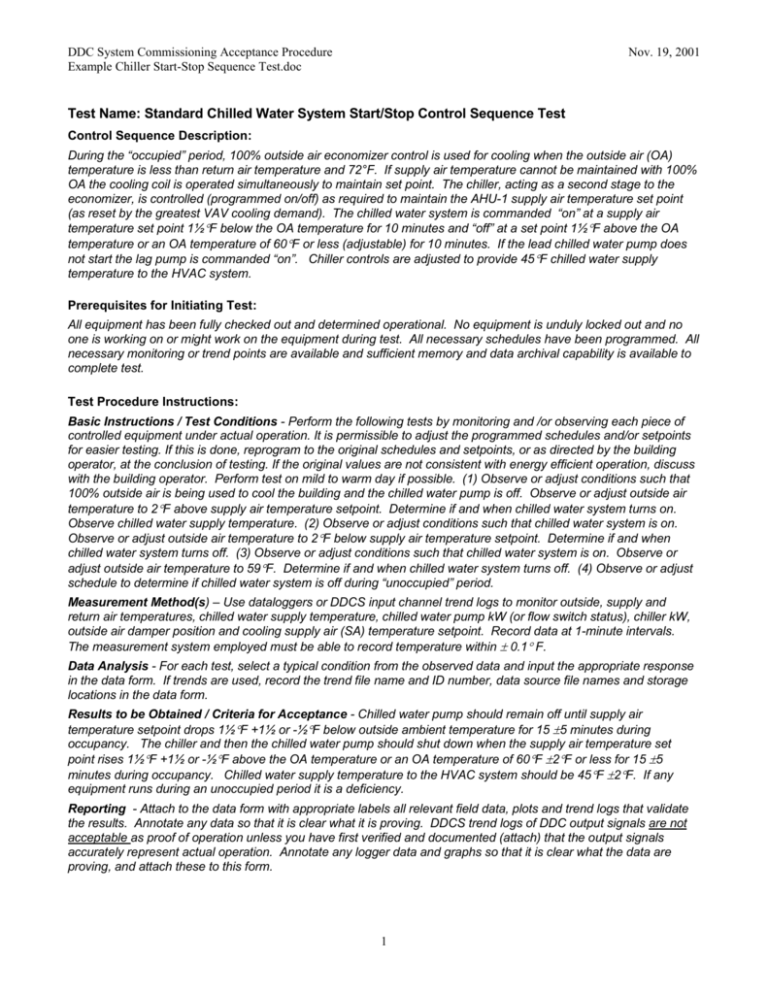
DDC System Commissioning Acceptance Procedure Example Chiller Start-Stop Sequence Test.doc Nov. 19, 2001 Test Name: Standard Chilled Water System Start/Stop Control Sequence Test Control Sequence Description: During the “occupied” period, 100% outside air economizer control is used for cooling when the outside air (OA) temperature is less than return air temperature and 72°F. If supply air temperature cannot be maintained with 100% OA the cooling coil is operated simultaneously to maintain set point. The chiller, acting as a second stage to the economizer, is controlled (programmed on/off) as required to maintain the AHU-1 supply air temperature set point (as reset by the greatest VAV cooling demand). The chilled water system is commanded “on” at a supply air temperature set point 1½F below the OA temperature for 10 minutes and “off” at a set point 1½F above the OA temperature or an OA temperature of 60F or less (adjustable) for 10 minutes. If the lead chilled water pump does not start the lag pump is commanded “on”. Chiller controls are adjusted to provide 45F chilled water supply temperature to the HVAC system. Prerequisites for Initiating Test: All equipment has been fully checked out and determined operational. No equipment is unduly locked out and no one is working on or might work on the equipment during test. All necessary schedules have been programmed. All necessary monitoring or trend points are available and sufficient memory and data archival capability is available to complete test. Test Procedure Instructions: Basic Instructions / Test Conditions - Perform the following tests by monitoring and /or observing each piece of controlled equipment under actual operation. It is permissible to adjust the programmed schedules and/or setpoints for easier testing. If this is done, reprogram to the original schedules and setpoints, or as directed by the building operator, at the conclusion of testing. If the original values are not consistent with energy efficient operation, discuss with the building operator. Perform test on mild to warm day if possible. (1) Observe or adjust conditions such that 100% outside air is being used to cool the building and the chilled water pump is off. Observe or adjust outside air temperature to 2F above supply air temperature setpoint. Determine if and when chilled water system turns on. Observe chilled water supply temperature. (2) Observe or adjust conditions such that chilled water system is on. Observe or adjust outside air temperature to 2F below supply air temperature setpoint. Determine if and when chilled water system turns off. (3) Observe or adjust conditions such that chilled water system is on. Observe or adjust outside air temperature to 59F. Determine if and when chilled water system turns off. (4) Observe or adjust schedule to determine if chilled water system is off during “unoccupied” period. Measurement Method(s) – Use dataloggers or DDCS input channel trend logs to monitor outside, supply and return air temperatures, chilled water supply temperature, chilled water pump kW (or flow switch status), chiller kW, outside air damper position and cooling supply air (SA) temperature setpoint. Record data at 1-minute intervals. The measurement system employed must be able to record temperature within 0.1 F. Data Analysis - For each test, select a typical condition from the observed data and input the appropriate response in the data form. If trends are used, record the trend file name and ID number, data source file names and storage locations in the data form. Results to be Obtained / Criteria for Acceptance - Chilled water pump should remain off until supply air temperature setpoint drops 1½F +1½ or -½F below outside ambient temperature for 15 5 minutes during occupancy. The chiller and then the chilled water pump should shut down when the supply air temperature set point rises 1½F +1½ or -½F above the OA temperature or an OA temperature of 60F 2F or less for 15 5 minutes during occupancy. Chilled water supply temperature to the HVAC system should be 45F 2F. If any equipment runs during an unoccupied period it is a deficiency. Reporting - Attach to the data form with appropriate labels all relevant field data, plots and trend logs that validate the results. Annotate any data so that it is clear what it is proving. DDCS trend logs of DDC output signals are not acceptable as proof of operation unless you have first verified and documented (attach) that the output signals accurately represent actual operation. Annotate any logger data and graphs so that it is clear what the data are proving, and attach these to this form. 1 DDC System Commissioning Acceptance Procedure Example Chiller Start-Stop Sequence Test.doc Nov. 19, 2001 Notes of Caution: To ensure that this Commissioning Procedure will not damage any equipment or affect any equipment warranties, have the equipment manufacturer’s representative review all test procedures prior to execution. Make all necessary parties aware of the test and that the equipment should not be disturbed. 2 DDC System Commissioning Acceptance Procedure Example Chiller Start-Stop Sequence Test.doc Nov. 19, 2001 Results/Observations Table: Name and affiliation of party conducting test: Start & stop time and date of test: Conditions during test: ____________________________________________________________________________ ________________________________________________________________________________________________ Related Equipment # or ID: Method of Test (1) Observe or adjust conditions such that 100% outside air is being used to cool the building and the chilled water pump is off. Observe or adjust outside air temperature to 2F above supply air temperature setpoint. Determine if and when chilled water system turns on. Observe chilled water supply temperature. AHU-1 ChWP 1/.2 Chiller 1 Test Data Time: ChWP Status: OAT: SAT Setpoint: Minutes until chiller on: Ent / Lvg CHW temp: (2) Observe or adjust conditions such that chilled water system is on. Observe or adjust outside air temperature to 2F below supply air temperature setpoint. Determine if and when chilled water system turns off. Time: ChWP Status: OAT: SAT Setpoint: Minutes until chiller off: Minutes until ChWP off: (3) Observe or adjust conditions such that chilled water system is on. Observe or adjust outside air temperature to 59F. Determine if and when chilled water system turns off. Time: ChWP Status: OAT: SAT Setpoint: Minutes until chiller off: Minutes until ChWP off: (4) Observe or adjust schedule to determine if is off during “unoccupied” period. Time: Schedule: Unoccupied ChWP Status: OK? Comment # / Data file name(s): Data file storage location: Plot name(s): Observations, notes, deficiencies, and recommendations: # Comment (attach additional sheets as required) __ ____________________________________________________________________________________________ __ ____________________________________________________________________________________________ __ ____________________________________________________________________________________________ Recommend Acceptance: Yes □ No □ Signature: Date: Attach to this form with labels all relevant field data, plots and trend logs that validate the results. Annotate any data so that it is clear what it is proving. 3
