General description of hydronic building heating system

Hydronic building heating system overview
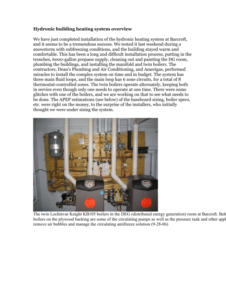
We have just completed installation of the hydronic heating system at Barcroft, and it seems to be a tremendous success. We tested it last weekend during a snowstorm with subfreezing conditions, and the building stayed warm and comfortable. This has been a long and difficult installation process, putting in the trenches, 6000-gallon propane supply, cleaning out and painting the DG room, plumbing the buildings, and installing the manifold and twin boilers. The contractors, Dean's Plumbing and Air Conditioning, and Amerigas, performed miracles to install the complex system on time and in budget. The system has three main fluid loops, and the main loop has 6 zone circuits, for a total of 8 thermostat-controlled zones. The twin boilers operate alternately, keeping both in service even though only one needs to operate at one time. There were some glitches with one of the boilers, and we are working on that to see what needs to be done. The APEP estimations (see below) of the baseboard sizing, boiler specs, etc. were right on the money, to the surprise of the installers, who initially thought we were under sizing the system.
The twin Lochinvar Knight KB105 boilers in the DEG (distributed energy generation) room at Barcroft. Behind the boilers on the plywood backing are some of the circulating pumps as well as the pressure tank and other appliances to remove air bubbles and manage the circulating antifreeze solution (9-28-06)
Electronic thermostat in the shop at Barcroft. There is an "off" setting if portions of the system need to be shut off during winter, for example. (9-28-06)
The separate zones are:
1.
shop and E lab
2.
dining room, kitchen, middle lab, and downstairs bath
3.
pantry
4.
west end lab and dorms, both upstairs and downstairs
5.
upstairs library, bath and bedroom
6.
upstairs TV room
7.
large animal building
8.
small animal building
There is a thermostat control box mounted in the main hallway by the office which tells which circuits are active with colored lights. We hope eventually to place a computer display beneath this box which will monitor the status of the entire energy system. A GIS map shows the hydronics in the Pace lab.
The boilers are digitally controlled and have a cat5 cable connector to a laptop.
The DEG room is spacious and clean, with room for a lot more installations. The conduits are completed to the small and large animal buildings, and we hope to complete the link to the astro-labs soon. We’re also working on the link up to the dome, planning a 480 volt connection there.
28-
06)
The propane tank field is installed 150' from the main building, and has 6000 gallons capacity of propane. A vapor and a liquid propane line run down to the DEG room. (9-28-06)
The DEG (distributed energy generation) room is approximately 33 feet long and 18 feet wide, and is presently designed to house the hydronics boilers, the micro turbine generators, and the inverter system. There will be plenty of room to add fuel cells and other energy technology units for testing and power generation in the future. The tubing along the walls is insulated "pex" tubing, carrying hot water out to the large animal building for heating purposes. (9-28-06)
This project has been difficult to implement owing to multiple emergencies
(multiple failures of the buried power line), shortage of staff, late opening dates, and long travel times for the contractors. Both contractors, Dean’s plumbing and heating, and Amerigas, were wonderful to work with and did excellent work. They installed and insulated about 2000 feet of pipe, snaking through narrow opening and around obstacles every foot of the way. The buried runs to the outbuildings used “insulpex” tubing, a new type of tubing specifically designed for the purpose.
Amerigas installed 6000 gallons of propane storage, including installation of a liquid propane feed from the tanks down to the DG room.
The Lochinvar company, manufacturers of the boilers, custom programmed circuit boards for the high elevation application. We hope to test the units’ efficiencies once we figure out how to measure and monitor things like propane consumption, etc. The boilers’ digital readouts should facilitate this.
The hydronic manifold has stubbed off locations for running a circuit to the future hot water storage tank. After consultation with Lochinvar and Western
Nevada Plumbing Supply (consultants for this project), we designed the hot water
(Thermal Energy Storage) tank circuit to run parallel to, rather than in series with, the boilers. Thus, when there is sufficiently hot water in the TES tanks, the boilers will not fire at all, saving propane.
We can be proud of the progress so far. It is not easy to design and build a complex system in such a unique environment. Barcroft now has a reliable, safe, efficient hydronic heating system (as opposed to relying on electric heaters which required large generator capacity and/or the underground grid connection, both of which are unreliable at Barcroft). The heating system is upgradeable to solar heating and reclamation of waste heat from the generators which will be installed next summer. The solar electric system, also to be installed next summer, will be able to power the heating system completely, so that the station will be able to run very efficiently using solar power and a minimum of propane. The multiple failures of the existing buried power line and diesel generator, while making progress difficult this summer, also highlighted the need and timeliness of the new system. We are planning on a fully functional off-grid power system by the end of October 2007, so hopefully some of these worries will be behind us a year from now.


