Machine operation monitor
advertisement
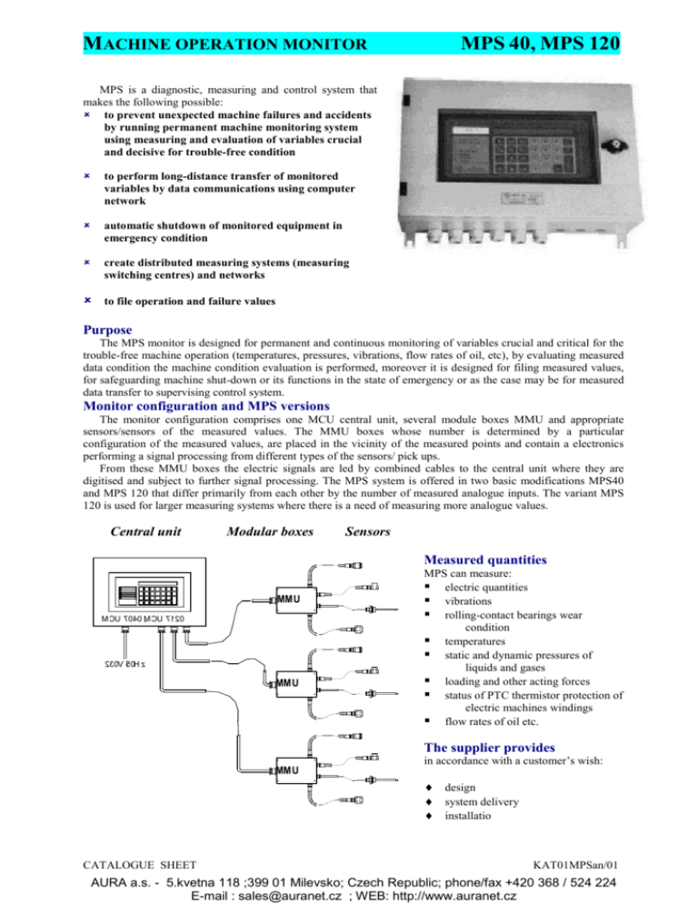
MACHINE OPERATION MONITOR MPS 40, MPS 120 MPS is a diagnostic, measuring and control system that makes the following possible: to prevent unexpected machine failures and accidents by running permanent machine monitoring system using measuring and evaluation of variables crucial and decisive for trouble-free condition to perform long-distance transfer of monitored variables by data communications using computer network automatic shutdown of monitored equipment in emergency condition create distributed measuring systems (measuring switching centres) and networks to file operation and failure values Purpose The MPS monitor is designed for permanent and continuous monitoring of variables crucial and critical for the trouble-free machine operation (temperatures, pressures, vibrations, flow rates of oil, etc), by evaluating measured data condition the machine condition evaluation is performed, moreover it is designed for filing measured values, for safeguarding machine shut-down or its functions in the state of emergency or as the case may be for measured data transfer to supervising control system. Monitor configuration and MPS versions The monitor configuration comprises one MCU central unit, several module boxes MMU and appropriate sensors/sensors of the measured values. The MMU boxes whose number is determined by a particular configuration of the measured values, are placed in the vicinity of the measured points and contain a electronics performing a signal processing from different types of the sensors/ pick ups. From these MMU boxes the electric signals are led by combined cables to the central unit where they are digitised and subject to further signal processing. The MPS system is offered in two basic modifications MPS40 and MPS 120 that differ primarily from each other by the number of measured analogue inputs. The variant MPS 120 is used for larger measuring systems where there is a need of measuring more analogue values. Central unit Modular boxes Sensors Measured quantities MM U M CU 7040 M , CU 7120 230V 5/ 0H z MM U MPS can measure: electric quantities vibrations rolling-contact bearings wear condition temperatures static and dynamic pressures of liquids and gases loading and other acting forces status of PTC thermistor protection of electric machines windings flow rates of oil etc. The supplier provides MM U in accordance with a customer’s wish: design system delivery installatio CATALOGUE SHEET KAT01MPSan/01 AURA a.s. - 5.kvetna 118 ;399 01 Milevsko; Czech Republic; phone/fax +420 368 / 524 224 E-mail : sales@auranet.cz ; WEB: http://www.auranet.cz MACHINE OPERATION MONITOR Basic technical data Central Unit MCU 7040 or MCU 7120 steel with glass lookingBox through MPS 40, MPS 120 Module Unit MMU Box ABS or PC plast Electric power supply 230 V/50 Hz, max. 30VA Electric power supply from the MCU central unit Operating ambient temperature -20C to +55C Operating ambient temperature -25C to +55C fro the AB7 for the AB7 environment environment Engineering desing Engineering desing according to ČSN 33 2000-3 according to ČSN 33 2000-3 Sealing IP 65 Sealing IP 65 Mass 12 kg Mass 1 kg Dimensions (h x w x d) 300 x 450 x 150 mm Dimensions (h x w x d) 120 x 160 x 91 mm 300 450 120 ø9 340 420 160 Tentiative technical parameters of the system inputs and outputs Equipment MPS 40 MPS 120 Function analog inputs vibration – effective velocity 12.5, 25, 50 mm/s in the range 10 Hz – 1 kHz bearing condition – conjugate acceleration temperatures – 50 to 100C, 0 to 500C 4 12 pressures, forces – range according to attached sensor DC voltage within the range of 20mV, 1 or 10 V DC current 0-20mA, 4-20mA resistor 0 to 105 bivalent inputs 8 8 inputs 12V to 24V/5mA with galvanic separation analog outputs 2 2 DC voltage 0 to 10V, DC current 4 to 20 mA relay outputs 7 7 voltage to 230V/2A serial communication 1 x RS232 for PC, modem or printer + optional RS channel 232, RS422 or RS485 for connecting mor units MCU 2 2 7xxx (with high-way repeaters to 13.2 km between units) alphanumeric display 2 x 40 2 x 40 displays oral state information regarding connected characters characters system, measured values indication LED diodes 8 8 colours: red, yellow, green – indicate the state of the measured system control keyboard 27 keys 27 keys for service actions when the monitor is being adjusted CATALOGUE SHEET KAT01MPSan/01 AURA a.s. - 5.kvetna 118 ;399 01 Milevsko; Czech Republic; phone/fax +420 368 / 524 224 E-mail : sales@auranet.cz ; WEB: http://www.auranet.cz
