Checklist #5 as constructed drawings Pine Rivers district
advertisement
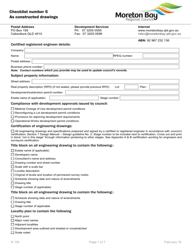
Checklist number 5 As constructed drawings Postal Address PO Box 159 Caboolture QLD 4510 Development Services Ph: 07 3205 0555 Fax: 07 3205 0599 Internet www.moretonbay.qld.gov.au mbrc@moretonbay.qld.gov.au ABN: 92 967 232 136 Certified registered engineer details: Company: Name: RPEQ number: Postal address: Business phone number: Note: Contact numbers which you provide may be used to update council’s records. Subject property information: Street address: Real property description (RPD) (if not sealed, please provide previous RPD): Lot: Plan: Development/subdivision permit number: Estate name (if applicable): Stage number: Compliance with development approvals issued by council: Material Change of Use development permit conditions Reconfiguring a Lot development permit conditions Provisions for adjoining development requirements Operational Works development permit conditions Certification of engineering drawings: All engineering drawings and specifications prepared and signed by a certified or registered engineer in accordance with council’s certification; Section 7 Design Manual – Design guideline No. 2; Stage number to be included next to certification. Cross out and print in block “not in this stage” through information pertaining to other stages. See Appendix A & B certification wording for engineers and surveyors certification. Title block on all engineering drawing to contain the following:: Estate name (if applicable) Developers name Consultant’s name and address Drawing number and sheet number Scale with a scale bar Locality description Original of levels and location of permanent survey marks Schedule showing date and nature of amendments Drawing title Stage number (if applicable) Title block on all engineering drawing to contain the following:: Schedule showing date and nature of amendments Drawing title Stage number (if applicable Locality plan to contain the following North point Major road names Adjacent localities Development area outlined and shaded or crosshatched Scale noted R 100 Page 1 of 7 February 16 Layout or stage plan drawings to include the following (if applicable): Layout of roads Approved road names Lot layout Lot numbers (as per survey plans) Stage boundaries clearly shown Lot dimensions and areas Easements North point All abandoned services that have been removed shown with a corresponding note Roadworks plans to include the following (if applicable): Road names and road reserve boundaries Lot boundaries, including easements Centreline or construction line showing Chainages Bearings Off sets if construction line is not the centreline of road All intersection points Information for each curve including: Tangent point chainages and offsets Curve radii Arc length Tangent length Super elevation (if applicable) Curve widening (if applicable) Kerb lines, including: Kerb radii (where not parallel to centreline) Tangent point chainages (where not parallel to centreline) Edge of pavement where no kerb is constructed Position and extent of channelisation Location and details of all traffic signs, guideposts, guardrail, and other road furniture, etc Pavement markings Catch pit, manhole and pipeline locations Full drainage details where not otherwise shown Location and levels of permanent marks or reference marks Concrete footpaths and cycle paths Location of access points, invert crossing, pram ramps, etc. and details North point on each plan view Changes in surfacing material Scale shown Intersection, cul-de-sac and speed control devices drawings to include the following (if applicable): Road names Kerb levels Pram ramp location Finished surface contours Channelisation details including set-out details, radii, etc Location of traffic signs, guide posts Linemarking (linemarking and signage may be shown on a separate plan) Speed control device details Section through medians/island etc. Details of construction methods for surfacing other than asphaltic concrete or sprayed bitumen Design vehicle paths shown on all LATM devices (intersections and mid block) Page 2 of 7 Feb-16 Road longitudinal sections drawings to include the following (if applicable): Road names Chainages on centreline (and construction line if used) Natural surface or peg levels Design road centreline levels Design grades Length and radii of vertical curves Chainage and levels at grade intersection points Chainage and levels at vertical curve tangent points Section through medians/island etc. Cut and/or fill depths Horizontal radii and tangent point chainages Kerb levels Total depth, and depth of pavement courses with CBR values or material used including design CBR Type and thickness of surfacing materials Road name, centreline and IP chainage of intersection side roads Road longitudinal sections drawings to include the following (if applicable): Standard format Road names Road reserve boundaries Road centreline or construction line Original natural surface line Constructed cross section shape Chainage on centreline or construction line together with natural surface level or peg level Offset to road centreline from peg line or construction line Cross fall batter slopes and dimensions where these differ to that shown on the type cross section Side drains shown No “open” cross sections - i.e. design and natural surface close All cross sections drawn in accordance with Department of Main Roads standard format Typical cross section shown for each road to include: Road names Road reserve width Road width between face of kerbs, or pavement width where no kerb is constructed Verge width Location and width of concrete footpath or cycle path, where constructed Off sets if construction line is not the centreline of road Crossfalls and/or grades of pavement, footpaths and batters etc with offsets to change of grade point Type and thickness of surfacing Total depth and depth of pavement courses with CBR values of material used or refer to details on plan Number: Position of subsoil drainage including notation regarding the extent of usage Accessway (to lots) cross sections to include the following (if applicable) Cross section showing offsets to change of grades, including grades and/or levels Any existing car accommodation or features Type and details of any surfacing to the access Road names and lot numbers being served Cross sections covers the full length of any surfacing or until the access ramps meet natural surface – whichever is the greater Page 3 of 7 Feb-16 Pathways and bikeways drawings to including the following (if applicable): All pathways clearly shown Chicanes provided to each end of all pathways Concrete path shown for all pathways linking to kerb Bikepaths clearly shown with widths as per permit or approval Drainage pathways Drainage pathway cross section Verge details to ends of drainage pathways Stormwater drainage catchment plan drawings to include the following (if applicable): Road name Existing and proposed property and road boundaries All catchments/sub-catchments called up according to the drainage calculation sheet Catchment/sub-catchment boundaries indicated by a bold line Proposed contours at a suitable interval Direction of watershed along the flow path given the longest time of concentration Stormwater reticulation schematic layout shown including manhole, inlet and outlet numbers (for urban catchments) All internal and external catchments shown to scale Stormwater drainage detail plan to include the following (if applicable): Detail of pipe junctions in manholes, where pipe centrelines are offset from centre point of manhole Full details including reinforcing of non-standard manholes Catchpit and field inlet locations (chainage offset, levels, etc.) Manhole locations (chainage, offset, levels, etc.) or tie to property boundary Culvert locations (chainage, offset, levels, etc.) Invert levels and diameters of pipe connections from catchpits to manholes Road name Roof water/inter-lot drainage plans to contain the following (if applicable): Road names Lot numbers as per survey plans Design surface levels Pit or inlet locations, surface levels and inlet and outlet invert levels Easements Roof water lines and kerb outlets under concrete footpath in verge Pipe diameter and type of pipe Pipe offset from boundaries House connection details, tie, length, diameter, IL and SL for each lot Drain line longitudinal sections (if applicable): Longitudinal sections for each line contain the following: Chainages Original natural surface levels Manhole and endwall chainages together with surface levels and inlet and outlet invert levels Distances between manholes/catchpits/endwalls Grade of each pipe section Diameter and class and material of each pipe section Outlet works to contain the following: Open drains Cross sections at each peg chainage (usually 20m intervals) Details of drop structures energy dissipaters, etc, (including top view, section views, etc) Page 4 of 7 Feb-16 Detention basin details to contain the following (if applicable): (if applicable): Plan view showing locality, road name Sectional views Details of basin wall construction Details of outlet structures (lot and high level outlets) Extent of any permanent storage Maximum storage level Extent and nature of any landscaping Inlet and outlet details Base slopes/crossfall shown Batter slopes shown Scour protection shown Silt management/runoff control works (if applicable): Plan layout/extent Typical device details/materials Design complies with QUDM Section 9.03.5 Temporary and permanent works indicated Notes on maintenance and operation Gross pollutant traps (if applicable): Plan layout/extent Long section and cross sections All materials specified/indicated Structural elements detailed Noise attenuation works (if applicable): Earthworks/mounds - plan, sections and batter slopes Barrier/fence details, typical, certified Landscaping Road names Drainage details Retaining walls and other building approvals (if applicable): Road names Lot numbers per survey plans Plan layout - extent Typical cross section Foundation details Drainage details Design and construction certified by appropriately experienced engineer Retaining walls and other building approvals (if applicable): Road names Lot numbers per survey plans Plan layout - extent Typical cross section Foundation details Drainage details Design and construction certified by appropriately experienced engineer Page 5 of 7 Feb-16 Landscaping plans drawings to include the following (if applicable): Road names Road reserve and property boundaries together with lot numbers Features bounding planting areas such as pathways, medians, etc Plan locations of trees and shrubs, etc called up from the schedule including spacings or area allowed between trees and shrubs Schedule of plant species with botanical and common names The position and type of any existing trees to be retained as part of landscaping or subdivisional works generally (excluding lot works) Construction details of any hard landscape elements, planter boxes, retaining walls, fences, etc Irrigation system details including valves, main line diameters and conduits Positions and extent of root intrusion barriers Details of improvement or modification General earthworks (fill plan) drawings to include the following (if applicable): Cut and fill areas clearly shown Pre and post contours (legend provided) Road and lot layout (indicate numbers) Road names Pit burn pit locations (if applicable) Plan certified by surveyor Water reticulation plan – drawings in accordance with council standard and to include the following (if applicable): Road reserve boundaries Road names Lot boundaries and numbers Location of all other existing and proposed services in footpath reserve Location of all constructed water lines, hydrants, valves tied to property boundary Kerb lines or pavement edge where no kerb exists Thrust block details Offset to mains, form property boundary at end, any bends and changes of offset Mains shown in accordance with MBRC standard line type for each diameter and legend Pipe type and class shown Standard notes to include: Cover Bedding Stainless steel fixings CR316 Use of DICL pipe where reduced cover is approved with class stated Reference to standard drawings Sewerage plan – drawings in accordance with council standard and to include the following (if applicable): Road names Contours provided Reference adjoining sheets Pipe size and type noted Any DICL sections shown Easements shown Lot numbers as per survey plans Offset to mains, form property boundary at end, any bends and changes of offset Page 6 of 7 Feb-16 Sewerage pump station (if applicable): General arrangement - drawings provided All details provided in accordance with MBRC standard drawings Electrical switchboard details in accordance with MBRC standard drawings All manuals and pump covers supplied to council’s Manager Electrical/Mechanical Services Appendix A: I: RPEQ number (engineers name) being a certified/registered engineer and duly authorised representative of: (consulting firm or company) Hereby certify the information contained in this drawing is an accurate as constructed representation of the works accept responsibility for the as constructed information contained in this drawing acknowledge the as constructed information contained in the drawing may be relied on by council and others Certification of stage: by (stage number) On (signature) (date) For (name of company) Note: Where consulting firms or company and stage numbers do not apply complete with N/A for not applicable Appendix B: (surveyor’s name) I: being a certified/registered engineer and duly authorised representative of: (company name) Hereby certify the information contained in this drawing is an accurate as constructed representation of the works accept responsibility for the as constructed information contained in this drawing acknowledge the as constructed information contained in the drawing may be relied on by council and others Certification of stage: by (stage number) On (signature) (date) For (name of company) Note: Where consulting firms or company and stage numbers do not apply complete with N/A for not applicable Privacy statement Moreton Bay Regional Council is collecting your personal information for the purpose of assessing your as constructed checklist. The collection of this information is authorised under the Sustainable Planning Act 2009. Your information will not be given to any other person or agency unless required by law. Page 7 of 7 Feb-16
